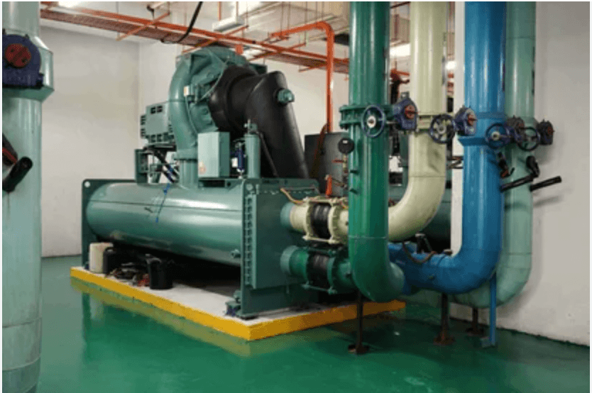
I have been working in the gas detection industry for the past seven years, and one of the most common questions I get is how to design a gas detection system for a chiller room. In this article, I will explain everything behind it.
A chiller room concentrates a large refrigerant charge into a small, often poorly ventilated space. When a seal fails, the room becomes hazardous long before anyone notices a smell or a pressure drop on the panel.
A properly designed gas detection system for a chiller room turns that silent failure into an alarm, a fan start, and a compressor trip in that order within seconds.
How to Design a Gas Detection System for a Chiller Room
This guide walks through the full design process: hazard identification, code selection, alarm setpoints, sensor technology, detector placement, controller architecture, interlocks, and commissioning.
Step 1: Identify the Refrigerant and the Hazard
Everything downstream depends on what is in the system and how much of it.
Pull the maximum charge of the largest single refrigerant circuit from the equipment nameplate or the P&ID. Then classify the hazard.
Ammonia (R717)
Toxic at low ppm and flammable at high concentration. Requires dual detection: ppm for life safety, %LEL for fire.
HFC and HFO refrigerants (R134a, R410A, R513A, R1234ze)
Primarily asphyxiants. A2L classes are mildly flammable and need additional consideration.
CO₂ (R744)
Asphyxiant and dangerous well below the concentration where anyone would notice it.
A room with 40 kg of R134a and a room with 4,000 kg of ammonia are entirely different design problems, even though both are “chiller rooms.”
Step 2: Confirm Which Codes Apply
Design the code that governs the site, not the one you know best.
ASHRAE 15 / 15.2
Machinery room refrigerant detection, alarm levels, and ventilation interlocks.
IIAR 2 and IIAR 6
Ammonia refrigeration system design and inspection.
EN 378 / ISO 5149
European and international refrigeration safety.
IMC Sections 1105–1106
Mechanical code refrigerant machinery room requirements.
ATEX, IECEx, or NEC Class I Div 2
If a flammable refrigerant places the room in a classified area
Local requirements often stack on top of these. In Mexico, for example, NOM-related requirements may apply alongside ASHRAE.
Step 3: Set the Alarm Thresholds
Setpoints define the entire cause-and-effect matrix. A typical ammonia machinery room configuration.
| Level | Setpoint | Action |
|---|---|---|
| Low | 25 ppm | Local alarm, BMS notification |
| Mid | 150 ppm | Emergency ventilation starts, audible and visual alarm |
| High | 300 ppm | Compressor shutdown, valve isolation, evacuation alarm |
| Fire | 25% LEL (≈3,750 ppm) | Full shutdown, fire alarm panel interface |
For halocarbons, set the upper alarm at the Refrigerant Concentration Limit (RCL) from ASHRAE 34 and add a lower early-warning setpoint, typically 100 to 1,000 ppm depending on the gas, so small leaks are caught before they become expensive ones.
For CO₂, use 5,000 ppm (the 8-hour TWA) as the low alarm and 15,000 to 30,000 ppm as the high alarm.
The most common setpoint error
Configuring only a %LEL alarm on a toxic gas. Ammonia harms people at 300 ppm. Its LEL alarm sits at roughly 3,750 ppm. By the time the flammability alarm trips, the room has been dangerous for a long time.
Step 4: Select the Right Sensor Technology
| Gas | Recommended Sensor | Practical Notes |
|---|---|---|
| Ammonia (ppm) | Electrochemical | 1–3 year cell life, cross-sensitive to H₂S and CO |
| Ammonia (%LEL) | Infrared preferred | Catalytic beads poison in oil-mist environments |
| Halocarbons | Infrared (NDIR) | Best selectivity and long-term stability |
| Halocarbons (budget) | Heated diode | Lower cost, noticeable drift, more frequent calibration |
| CO₂ | Infrared (NDIR) | Industry standard, stable |
| A2L flammables | IR or catalytic | Must be certified for the specific refrigerant |
Specify measuring range, T90 response time (under 30 seconds is a reasonable target), operating temperature and humidity range matched to the chiller room environment, and IP65 as a minimum enclosure rating.
Step 5: Place the Detectors Where the Gas Will Actually Go
Detector placement is where most chiller room gas detection systems fail
A correctly specified sensor mounted in the wrong place provides documentation, not protection.
Mounting height follows vapor density
- Ammonia is lighter than air (SG 0.6), but it is released cold and often behaves close to neutrally buoyant. Mount at 1.5–1.8 m for personnel exposure monitoring, and add a high-level detector near the ceiling or ventilation exhaust to catch accumulation.
- Halocarbons and CO₂ are heavier than air. Mount at 0.3–0.5 m above the finished floor, and cover low points, pits, and trenches.
Position relative to leak sources
Install detectors within 3 to 6 meters of the components that actually leak: compressor shaft seals, flanged joints, purge units, relief valve discharge points, oil pots, pump seals, and valve stations.
Cover the airflow path
Place one detector near the ventilation air inlet and one near the exhaust. Air movement carries the leak toward the exhaust. A detector there sees the plume before the room fills.
Avoid these locations
directly in the discharge of a fan or damper, immediately beside doorways where infiltration dilutes the sample, behind large obstructions, and in dead corners with no measurable air movement.
Add a pre-entry detector
A sensor outside the room entrance, or in the adjacent corridor, gives technicians a warning before they open the door.
Coverage density
One detector per 200–400 m² of floor area, or one per major equipment skid, whichever produces more detectors.
Step 6: Choose the Controller Architecture
Three common approaches:
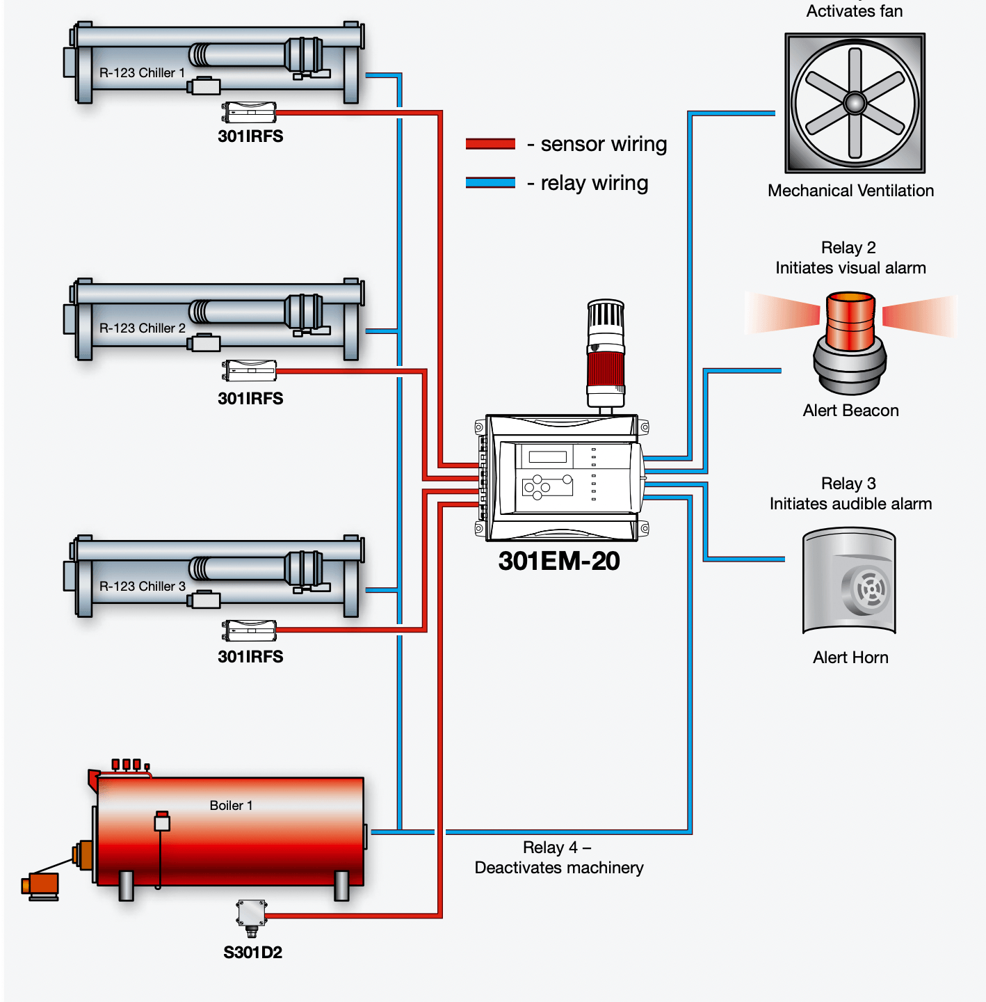
Standalone addressable controller with Modbus RTU or Modbus TCP output to the BMS. Simple, self-contained, easy to commission.
4–20 mA analog loops into a safety PLC. Best when the shutdown logic must sit inside an existing safety system.
Digital RS-485 bus with daisy-chained detectors. Far less cable, but plan the loop topology for redundancy so a single break does not blind multiple detectors.
Whichever you choose, the controller must:
- Fail-safe, annunciate sensor faults, open circuits, and loss of power as alarms, not as normal readings.
- Provide dedicated relay outputs for ventilation, shutdown, and alarm devices.
- Include standby power (30 minutes minimum; check your governing code).
- Log events with timestamps for compliance and incident investigation.
- Latch high-level alarms with manual reset, while low-level alarms auto-reset.
Step 7: Define the Interlocks
The detection system is only useful because of what it commands. Document this as a formal cause-and-effect matrix.
| Output | Function |
|---|---|
| Emergency ventilation | Start exhaust fans at mid-level alarm, sized per ASHRAE 15 or IIAR 2 |
| Refrigerant isolation | Close the motorized king valve or liquid line solenoid |
| Compressor shutdown | Hardwired trip contact to the motor control centre |
| Audible and visual alarm | Sounder and beacon inside the room and outside every entrance |
| BMS / SCADA | Modbus registers for live concentration, alarm state, and fault status |
| Fire alarm interface | Dry contact on %LEL alarm |
Emergency ventilation airflow for ammonia machinery rooms is calculated from the refrigerant charge under IIAR 2.
Coordinate this figure with the mechanical engineer rather than assuming a generic air change rate.
Step 8: Power and Wiring
- 24 VDC is standard; size the power supply for total detector load plus 25% headroom.
- Use shielded twisted pair with the shield grounded at the controller end only.
- Check voltage drop on long 4–20 mA runs. Keep it under 10% at the furthest detector.
- Route detection cabling in separate conduit, maintaining at least 300 mm from power cabling.
- Match cable gland ratings to the enclosure IP rating.
Step 9: Produce the Documentation Set
A complete design package includes the following:
- Detector location drawing overlaid on the room’s general arrangement.
- Cause-and-effect matrix mapping every input and setpoint to every output.
- I/O list with tag numbers, ranges, and Modbus addresses.
- Loop diagrams.
- Panel general arrangement and wiring schematics.
- Sensor datasheets and hazardous area certificates.
- Calibration and maintenance schedule.
Step 10: Commission and Maintain
Installation is not commissioning. Before handover
- Bump test every detector with certified span gas.
- Perform a full calibration on each sensor.
- Proof test the complete cause-and-effect matrix, including actual fan starts and compressor trips.
Ongoing
- Calibrate electrochemical sensors every 6 months, infrared every 12 months, or per manufacturer’s instructions.
- Replace electrochemical cells every 2–3 years; infrared sources typically last 5–10 years
- Retain all calibration records for audit.
- Run an annual full functional test covering ventilation and shutdown interlocks.
Five Design Mistakes That Keep Recurring
- Setting thresholds by LEL alone when the toxic exposure limit is an order of magnitude lower.
- Mounting halocarbon detectors at head height, where a heavier-than-air refrigerant will never reach them.
- Omitting a detector at the ventilation exhaust, so gradual accumulation is invisible to the system.
- Using catalytic bead sensors in oil-mist environments, where they are poisoned within months.
- Skipping the exterior beacon at room entrances, which most codes explicitly require.
Bringing It Together
A chiller room gas detection system is a chain: correct gas identification, code-compliant setpoints, appropriate sensor technology, physics-driven placement, fail-safe controls, and verified interlocks. A weak link anywhere breaks the chain, and the failure mode is silence.
Start with the refrigerant charge and the governing code. Everything else follows from those two facts.