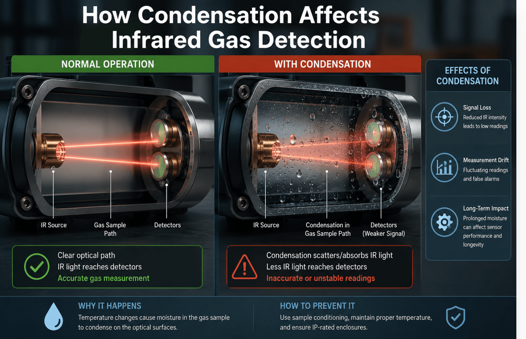
If you’ve worked with infrared gas detectors long enough, you’ve almost certainly been called out to investigate a “gas leak” that turned out to be nothing more than water.
Condensation is one of the most common and most misunderstood causes of nuisance faults, beam blocks, and degraded performance in IR gas detection systems.
In my years commissioning and maintaining gas detection systems in industrial facilities across Mexico, condensation-related issues come up constantly, especially in coastal plants, cooling tower areas, and anywhere equipment cycles between hot days and cold nights.
This article explains exactly how condensation affects infrared gas detection, why it happens, and the practical steps that prevent it.
Why Infrared Detectors Are Sensitive to Moisture
Infrared gas detection, whether point-type NDIR or open-path, works on a simple optical principle: a beam of infrared light passes through a sample of air, and target gases (typically hydrocarbons or CO₂) absorb specific IR wavelengths.
The detector compares the energy received at the measurement wavelength with that at a reference wavelength that the target gas doesn’t absorb. The difference tells the instrument how much gas is present.
That optical path is the system’s greatest strength and its greatest vulnerability. Anything that interferes with light transmission, such as dust, oil film, ice, or water droplets, changes the amount of IR energy reaching the receiver. Condensation is uniquely troublesome because
Water absorbs infrared energy broadly
Liquid water and water vapor absorb across large portions of the IR spectrum, including regions near common hydrocarbon measurement bands (around 3.3 µm) and CO₂ bands (around 4.26 µm).
Droplets scatter light
Even where water doesn’t absorb strongly, condensed droplets on a lens or mirror scatter the beam, reducing signal at both the measurement and reference wavelengths.
It forms fast and disappears without a trace
A detector can fog up at 3 a.m., throw a fault, and be perfectly dry by the time a technician arrives at 9 a.m., which is why condensation problems are so often misdiagnosed.
What Actually Happens When Condensation Forms on IR Optics
The effect depends on where the water forms and how the detector’s compensation system handles it.
Beam block and low-signal faults
The most common symptom. When enough water accumulates on the optical windows, mirrors, or retroreflector (in open-path systems), total IR energy drops below the detector’s minimum threshold.
Well-designed instruments respond with a beam block or “low signal” fault rather than a gas reading; the dual-wavelength design recognizes that both channels dropped, which gas absorption wouldn’t cause.
This is the fail-safe outcome, but it still means your detector is offline. In a facility relying on that point for permit-to-work or ESD logic, a beam block at dawn every day is an operational problem, not just an annoyance.
False or unstable gas readings
Less common but more dangerous territory. If condensation affects the measurement and reference wavelengths unevenly, for example, a thin water film with dissolved contaminants or partial fogging on one optical element, the ratio between channels shifts. Depending on the instrument, this can produce the following:
- Drifting baseline readings (a few % LEL that comes and goes with humidity)
- Negative readings after the condensation clears
- Reduced sensitivity: the detector still responds to gas, but under-reads
Modern detectors from major manufacturers compensate well for uniform attenuation, but no compensation scheme is perfect against non-uniform films or droplets sitting directly in the beam path.
Long-term optical degradation
Repeated condensation cycles leave behind residue. Water evaporates; dissolved salts, dust, and process contaminants don’t.
Over months, this builds a haze on optical surfaces that permanently reduces signal margin. In coastal or marine environments, salt-laden condensation is especially aggressive.
It’s hygroscopic, so it pulls moisture back onto the optics even in conditions where clean surfaces would stay dry.
Water ingress and electronics damage
Condensation isn’t only an optical problem. If it forms inside the enclosure, usually because a gland wasn’t sealed properly or a breather drain was omitted, you get corrosion on PCBs, connector failures, and erratic behavior that looks nothing like a moisture issue. Internal condensation is a killer of otherwise healthy detectors.
When and Where Condensation Forms
Condensation appears whenever a surface falls below the dew point of the surrounding air. In gas detection installations, the classic triggers are the following.
| Scenario | Why It Causes Condensation | Typical Symptom |
|---|---|---|
| Day/night temperature swings | The detector housing cools overnight below the dew point of humid air | Beam block faults in early morning that self-clear |
| Cooling towers, scrubbers, steam vents nearby | Locally saturated air contacts cooler detector optics | Chronic fogging, frequent cleaning needed |
| Air-conditioned enclosures venting near detectors | A cold detector surface meets warm humid outdoor air | Faults during hot, humid afternoons |
| Coastal/tropical climates | Sustained high humidity, salt aerosols | Optical haze, corrosion, recurring faults |
| Washdown areas (food, pharma) | Direct water spray plus high ambient humidity | Beam blocks during and after cleaning cycles |
| Rapid weather fronts / rain after heat | Sudden dew point rise over cool equipment | Multiple detectors faulting simultaneously |
That last row is worth noting: if several IR detectors across a site fault at the same time after a weather change, condensation is almost always the cause; real gas releases don’t behave that way.
Open-Path vs. Point IR Detectors: Different Vulnerabilities
Open-path infrared (OPIR) systems send a beam across tens or hundreds of meters between a transmitter and receiver (or retroreflector).
They have more exposed optical surfaces and are also affected by fog, rain, and mist in the beam path itself, not just on the optics.
Heavy fog can attenuate the beam enough to trigger beam block even with perfectly clean windows.
Good OPIR designs distinguish between gradual obscuration (dirty optics maintenance warning) and total block (fault), but condensation sits awkwardly between the two.
Point IR (NDIR) detectors have a short internal optical path protected by a weather baffle and hydrophobic filter.
They’re far more tolerant of ambient fog, but the small measurement cavity means even a little condensation on the internal mirror or windows has an outsized effect.
Point IR detectors mounted in cold spots on uninsulated steel near grade, for example, are frequent offenders.
If you’re still deciding between architectures for a humid site, this trade-off matters as much as coverage geometry. (See our guide on fixed vs. portable and point vs. open-path detection strategies for the full comparison.)
How Manufacturers Fight Condensation
Modern IR detectors include several defenses worth understanding, because they affect both product selection and installation:
Heated optics
The most effective measure. A small heater keeps optical windows and mirrors a few degrees above ambient, so surfaces stay above dew point.
Nearly all serious fixed-point IR and OPIR detectors for outdoor use include this; verify it’s specified and, critically, that the detector is actually powered continuously so the heater works. Detectors powered down overnight lose this protection exactly when they need it most.
Hydrophobic coatings and baffles
Optical windows treated with hydrophobic coatings shed water as beads rather than films. Weather baffles and sintered or membrane filters keep bulk water spray out while allowing gas diffusion.
These help, but coatings degrade; never wipe optics with abrasive materials or aggressive solvents during cleaning.
Dual-wavelength compensation
As described above, the reference channel lets the instrument ignore attenuation that affects both wavelengths equally.
This is why IR detectors handle gradual dirt accumulation gracefully and why the technology is inherently more condensation-tolerant than older single-beam designs.
Enclosure breathers and drains
For the internal condensation problem, certified breather drains allow pressure equalization and let accumulated moisture escape without compromising the Ex rating.
If your detectors or junction boxes in humid areas don’t have them, that’s a retrofit worth budgeting.
Field-Proven Prevention Practices
From an installation and maintenance standpoint, these are the measures that actually reduce condensation callouts:
Mind the mounting location
Avoid mounting detectors directly downwind of cooling towers, steam traps, or scrubber exhausts. A relocation of two or three meters often eliminates chronic fogging.
Keep detectors continuously powered
Optics heaters only work when energized. Sites that de-energize field instrumentation during shutdowns often see a wave of beam blocks on restart.
Orient correctly
Follow the manufacturer’s orientation requirements (usually horizontal, weather baffle down). Incorrect orientation lets water pool against optical surfaces instead of draining.
Use sunshades/weather shields
They reduce radiative cooling at night, a major driver of below-dew-point surfaces as well as daytime solar heating.
Seal glands and fit breather drains
Internal condensation is an installation-quality problem. Every unused entry plugged, every gland torqued, and a breather drained at the low point.
Clean optics on a schedule, correctly
Use the manufacturer-approved cloth and cleaner. In salty or dusty environments, shorten the interval.
Log the received signal strength (most detectors report it), and trend it. A slow decline tells you cleaning frequency needs to increase before faults start.
Bump test after cleaning
Cleaning optics changes the optical baseline on some instruments. A quick functional check confirms the detector still responds correctly. Our calibration and bump testing guide covers the procedure in detail.
Condensation vs. Real Gas: How to Tell the Difference
When investigating an event, these patterns point to condensation rather than gas:
- A fault or reading occurred in early morning or immediately after a weather change
- Multiple detectors in different process areas alarmed or faulted simultaneously
- The instrument logged a beam block / low signal fault rather than a gas concentration
- The event self-cleared as ambient temperature rose
- No corroborating reading from nearby catalytic bead, electrochemical, or portable detectors
None of these justify ignoring an alarm; always respond per procedure, but they should drive the root-cause investigation toward environmental factors before anyone starts hunting for a phantom leak.
FAQ
Can condensation cause a false gas alarm on an infrared detector?
It’s uncommon but possible. Uniform fogging typically causes a beam block fault, not a gas reading, thanks to dual-wavelength compensation.
However, non-uniform water films or contaminated droplets can unbalance the measurement and reference channels enough to produce erratic or false readings on some instruments.
Why does my IR gas detector fault every morning?
Overnight radiative cooling drops the detector’s optical surfaces below the dew point, and condensation forms until the sun warms things up.
Check that the detector is continuously powered (so its optics heater works), fit a weather shield, and verify correct mounting orientation.
Does humidity alone affect infrared gas detectors?
Water vapor has some IR absorption near common measurement bands, but modern detectors are designed and compensated for the full 0–100% RH range.
Problems begin when vapor becomes liquid; condensing humidity, not high humidity itself, is the real enemy.
Are catalytic bead detectors better than IR in humid environments?
Not generally. Catalytic sensors have their own moisture issues (sinter blockage, thermal shock from water spray) plus vulnerabilities IR doesn’t share, like catalyst poisoning. IR with heated optics is usually the better choice for humid sites; the key is proper installation.
How do I clean condensation residue off IR detector optics?
Use only the lint-free materials and cleaning solution specified by the manufacturer — typically a mild soap solution or isopropyl alcohol on approved surfaces.
Never use abrasives or strong solvents, which damage hydrophobic coatings. Verify signal strength and bump test after cleaning.
2 thoughts on “How Condensation Affects Infrared Gas Detection”