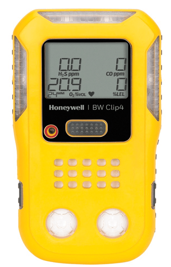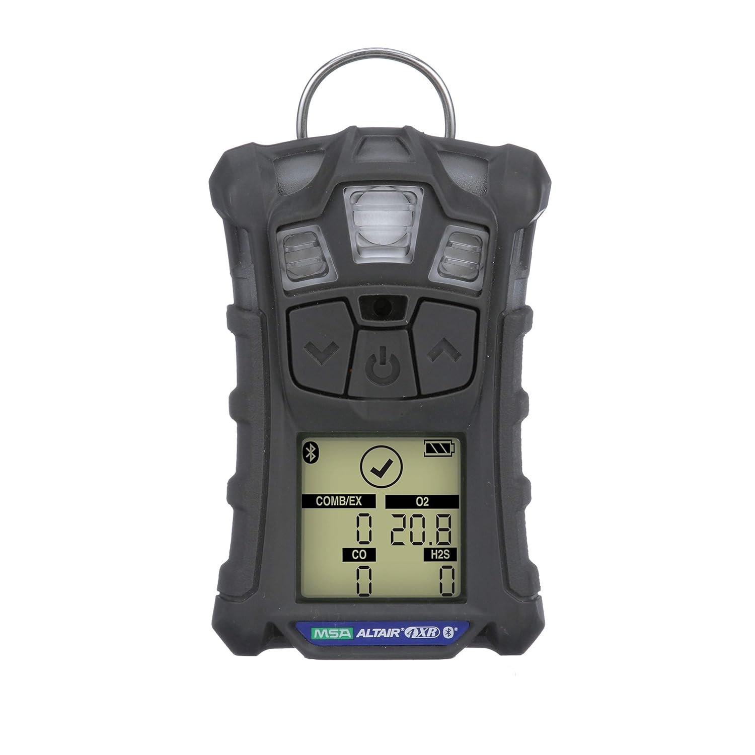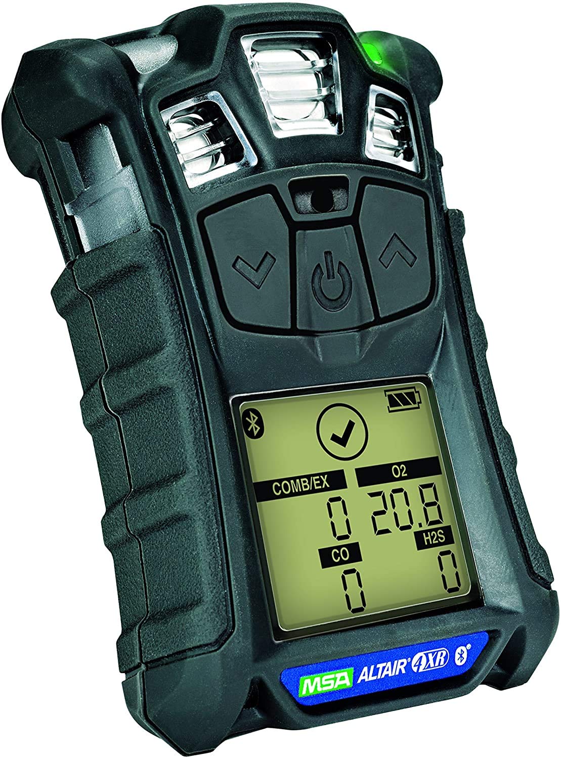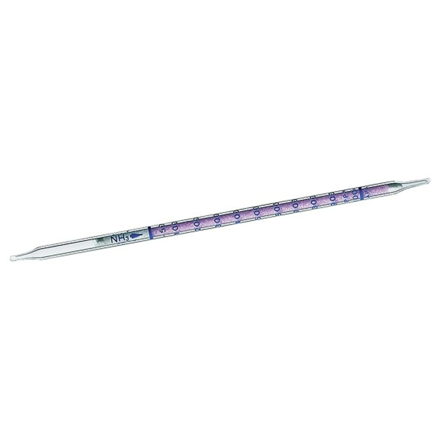
How to Design a Gas Detection System for a Chiller Room

I have been working in the gas detection industry for the past seven years, and one of the most common questions I get is how to design a gas detection system for a chiller room. In this article, I will explain everything behind it.

A chiller room concentrates a large refrigerant charge into a small, often poorly ventilated space. When a seal fails, the room becomes hazardous long before anyone notices a smell or a pressure drop on the panel.

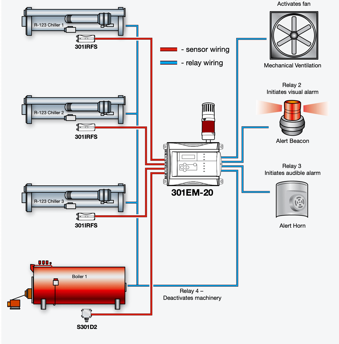
A properly designed gas detection system for a chiller room turns that silent failure into an alarm, a fan start, and a compressor trip in that order within seconds.

How to Design a Gas Detection System for a Chiller Room

This guide walks through the full design process: hazard identification, code selection, alarm setpoints, sensor technology, detector placement, controller architecture, interlocks, and commissioning.

Step 1: Identify the Refrigerant and the Hazard

Everything downstream depends on what is in the system and how much of it.

Pull the maximum charge of the largest single refrigerant circuit from the equipment nameplate or the P&ID. Then classify the hazard.

Ammonia (R717)

Toxic at low ppm and flammable at high concentration. Requires dual detection: ppm for life safety, %LEL for fire.

HFC and HFO refrigerants (R134a, R410A, R513A, R1234ze)

Primarily asphyxiants. A2L classes are mildly flammable and need additional consideration.

CO₂ (R744)

Asphyxiant and dangerous well below the concentration where anyone would notice it.

A room with 40 kg of R134a and a room with 4,000 kg of ammonia are entirely different design problems, even though both are “chiller rooms.”

Step 2: Confirm Which Codes Apply

Design the code that governs the site, not the one you know best.

ASHRAE 15 / 15.2

Machinery room refrigerant detection, alarm levels, and ventilation interlocks.

IIAR 2 and IIAR 6

Ammonia refrigeration system design and inspection.

EN 378 / ISO 5149

European and international refrigeration safety.

IMC Sections 1105–1106

Mechanical code refrigerant machinery room requirements.

ATEX, IECEx, or NEC Class I Div 2

If a flammable refrigerant places the room in a classified area

Local requirements often stack on top of these. In Mexico, for example, NOM-related requirements may apply alongside ASHRAE.

Step 3: Set the Alarm Thresholds

Setpoints define the entire cause-and-effect matrix. A typical ammonia machinery room configuration.

LevelSetpointAction
Low25 ppmLocal alarm, BMS notification
Mid150 ppmEmergency ventilation starts, audible and visual alarm
High300 ppmCompressor shutdown, valve isolation, evacuation alarm
Fire25% LEL (≈3,750 ppm)Full shutdown, fire alarm panel interface

For halocarbons, set the upper alarm at the Refrigerant Concentration Limit (RCL) from ASHRAE 34 and add a lower early-warning setpoint, typically 100 to 1,000 ppm depending on the gas, so small leaks are caught before they become expensive ones.

For CO₂, use 5,000 ppm (the 8-hour TWA) as the low alarm and 15,000 to 30,000 ppm as the high alarm.

The most common setpoint error

Configuring only a %LEL alarm on a toxic gas. Ammonia harms people at 300 ppm. Its LEL alarm sits at roughly 3,750 ppm. By the time the flammability alarm trips, the room has been dangerous for a long time.

Step 4: Select the Right Sensor Technology

GasRecommended SensorPractical Notes
Ammonia (ppm)Electrochemical1–3 year cell life, cross-sensitive to H₂S and CO
Ammonia (%LEL)Infrared preferredCatalytic beads poison in oil-mist environments
HalocarbonsInfrared (NDIR)Best selectivity and long-term stability
Halocarbons (budget)Heated diodeLower cost, noticeable drift, more frequent calibration
CO₂Infrared (NDIR)Industry standard, stable
A2L flammablesIR or catalyticMust be certified for the specific refrigerant

Specify measuring range, T90 response time (under 30 seconds is a reasonable target), operating temperature and humidity range matched to the chiller room environment, and IP65 as a minimum enclosure rating.

Step 5: Place the Detectors Where the Gas Will Actually Go

Detector placement is where most chiller room gas detection systems fail

A correctly specified sensor mounted in the wrong place provides documentation, not protection.

Mounting height follows vapor density

  • Ammonia is lighter than air (SG 0.6), but it is released cold and often behaves close to neutrally buoyant. Mount at 1.5–1.8 m for personnel exposure monitoring, and add a high-level detector near the ceiling or ventilation exhaust to catch accumulation.
  • Halocarbons and CO₂ are heavier than air. Mount at 0.3–0.5 m above the finished floor, and cover low points, pits, and trenches.

Position relative to leak sources

Install detectors within 3 to 6 meters of the components that actually leak: compressor shaft seals, flanged joints, purge units, relief valve discharge points, oil pots, pump seals, and valve stations.

Cover the airflow path

Place one detector near the ventilation air inlet and one near the exhaust. Air movement carries the leak toward the exhaust. A detector there sees the plume before the room fills.

Avoid these locations

directly in the discharge of a fan or damper, immediately beside doorways where infiltration dilutes the sample, behind large obstructions, and in dead corners with no measurable air movement.

Add a pre-entry detector

A sensor outside the room entrance, or in the adjacent corridor, gives technicians a warning before they open the door.

Coverage density

One detector per 200–400 m² of floor area, or one per major equipment skid, whichever produces more detectors.

Step 6: Choose the Controller Architecture

Three common approaches:

Standalone addressable controller with Modbus RTU or Modbus TCP output to the BMS. Simple, self-contained, easy to commission.

4–20 mA analog loops into a safety PLC. Best when the shutdown logic must sit inside an existing safety system.

Digital RS-485 bus with daisy-chained detectors. Far less cable, but plan the loop topology for redundancy so a single break does not blind multiple detectors.

    Whichever you choose, the controller must:

    • Fail-safe, annunciate sensor faults, open circuits, and loss of power as alarms, not as normal readings.
    • Provide dedicated relay outputs for ventilation, shutdown, and alarm devices.
    • Include standby power (30 minutes minimum; check your governing code).
    • Log events with timestamps for compliance and incident investigation.
    • Latch high-level alarms with manual reset, while low-level alarms auto-reset.

    Step 7: Define the Interlocks

    The detection system is only useful because of what it commands. Document this as a formal cause-and-effect matrix.

    OutputFunction
    Emergency ventilationStart exhaust fans at mid-level alarm, sized per ASHRAE 15 or IIAR 2
    Refrigerant isolationClose the motorized king valve or liquid line solenoid
    Compressor shutdownHardwired trip contact to the motor control centre
    Audible and visual alarmSounder and beacon inside the room and outside every entrance
    BMS / SCADAModbus registers for live concentration, alarm state, and fault status
    Fire alarm interfaceDry contact on %LEL alarm

    Emergency ventilation airflow for ammonia machinery rooms is calculated from the refrigerant charge under IIAR 2.

    Coordinate this figure with the mechanical engineer rather than assuming a generic air change rate.

    Step 8: Power and Wiring

    • 24 VDC is standard; size the power supply for total detector load plus 25% headroom.
    • Use shielded twisted pair with the shield grounded at the controller end only.
    • Check voltage drop on long 4–20 mA runs. Keep it under 10% at the furthest detector.
    • Route detection cabling in separate conduit, maintaining at least 300 mm from power cabling.
    • Match cable gland ratings to the enclosure IP rating.

    Step 9: Produce the Documentation Set

    A complete design package includes the following:

    • Detector location drawing overlaid on the room’s general arrangement.
    • Cause-and-effect matrix mapping every input and setpoint to every output.
    • I/O list with tag numbers, ranges, and Modbus addresses.
    • Loop diagrams.
    • Panel general arrangement and wiring schematics.
    • Sensor datasheets and hazardous area certificates.
    • Calibration and maintenance schedule.

    Step 10: Commission and Maintain

    Installation is not commissioning. Before handover

    • Bump test every detector with certified span gas.
    • Perform a full calibration on each sensor.
    • Proof test the complete cause-and-effect matrix, including actual fan starts and compressor trips.

    Ongoing

    • Calibrate electrochemical sensors every 6 months, infrared every 12 months, or per manufacturer’s instructions.
    • Replace electrochemical cells every 2–3 years; infrared sources typically last 5–10 years
    • Retain all calibration records for audit.
    • Run an annual full functional test covering ventilation and shutdown interlocks.

    Five Design Mistakes That Keep Recurring

    1. Setting thresholds by LEL alone when the toxic exposure limit is an order of magnitude lower.
    2. Mounting halocarbon detectors at head height, where a heavier-than-air refrigerant will never reach them.
    3. Omitting a detector at the ventilation exhaust, so gradual accumulation is invisible to the system.
    4. Using catalytic bead sensors in oil-mist environments, where they are poisoned within months.
    5. Skipping the exterior beacon at room entrances, which most codes explicitly require.

    Bringing It Together

    A chiller room gas detection system is a chain: correct gas identification, code-compliant setpoints, appropriate sensor technology, physics-driven placement, fail-safe controls, and verified interlocks. A weak link anywhere breaks the chain, and the failure mode is silence.

    Start with the refrigerant charge and the governing code. Everything else follows from those two facts.

    Why Do Catalytic Gas Sensors Become Poisoned?

    If you work with combustible gas detection long enough, you will eventually run into a detector that looks perfectly healthy, powers up normally, passes a visual inspection, and yet completely fails to respond to gas.

    In my experience commissioning and servicing gas detection systems in industrial plants, the most common culprit behind this silent failure is catalytic gas sensor poisoning.

    Catalytic gas sensors become poisoned when certain airborne compounds most notoriously silicones, sulfur compounds, lead, and phosphorus-based chemicals react with or coat the sensor’s catalytic bead, permanently destroying or blocking the active sites where combustible gas is supposed to oxidize.

    The sensor gradually and invisibly loses sensitivity, which is exactly what makes poisoning one of the most dangerous failure modes in gas detection.

    In this article, I’ll break down how catalytic (pellistor) sensors actually work, the specific chemicals that poison them, the difference between poisoning and inhibition, and the field practices that protect both your sensors and your people.

    How Catalytic Bead (Pellistor) Sensors Work

    To understand poisoning, you first need to understand what’s happening inside the sensor.

    A catalytic bead sensor, often called a pellistor, contains two small ceramic beads, each wound around a platinum coil and wired into a Wheatstone bridge circuit:

    • The active bead is coated with a catalyst (typically palladium or platinum-based) that allows combustible gas to oxidize on its surface at a much lower temperature than open-flame combustion.
    • The reference (compensator) bead is chemically identical but has no catalyst or is treated to be inert. Its job is to compensate for changes in ambient temperature, humidity, and pressure.

    Both beads are heated to roughly 400–500°C. When a combustible gas such as methane, propane, or hydrogen reaches the active bead, it oxidizes (“burns”) on the catalytic surface.

    That combustion releases heat, raising the bead’s temperature and therefore the electrical resistance of its platinum coil.

    The Wheatstone bridge measures the resistance imbalance between the active and reference beads, and that imbalance is converted into a gas concentration reading usually expressed as a percentage of the Lower Explosive Limit (%LEL).

    The entire measurement principle depends on one thing: the catalyst surface must stay chemically active and physically accessible. Poisoning attacks exactly that.

    What Sensor Poisoning Actually Is

    Sensor poisoning is the permanent, irreversible loss of catalytic activity caused by chemical compounds that either coat the catalyst surface or react with the catalyst material itself.

    The word “permanent” matters. A poisoned pellistor cannot be recovered by recalibration, cleaning, or bake-out. Once the active sites are destroyed or buried, the sensor element must be replaced.

    This is distinct from inhibition, which we’ll cover below, a temporary loss of sensitivity that can partially or fully recover once the contaminant is removed.

    Why Poisoning Is So Dangerous: The “Fail-Dangerous” Problem

    Most electronic failures announce themselves. A broken coil, an open circuit, or a dead sensor typically triggers a fault alarm on the controller or instrument.

    Poisoning does not.

    A poisoned catalytic sensor keeps producing a stable, believable output, usually a clean 0% LEL because electrically, nothing is wrong.

    The Wheatstone bridge is balanced, the beads are heated, and the circuit is happy. The sensor simply no longer responds to gas or responds at a fraction of its calibrated sensitivity.

    This is what safety engineers call a fail-dangerous or fail-to-danger condition: the instrument fails in a way that hides the hazard instead of revealing it.

    I’ve pulled sensors from the field that read a perfect zero in a functional test atmosphere of 50% LEL methane.

    On the control room display, that detector had looked “fine” for months. That is the core reason regular bump testing is non-negotiable, and we’ll come back to it.

    The Main Causes of Catalytic Gas Sensor Poisoning

    Not all contaminants are equal. Here are the compound families that engineers in the field worry about most, roughly in order of how often they cause real-world problems.

    Silicones: The #1 Poison in Industrial Environments

    Silicone compounds are by far the most common and most aggressive pellistor poison, and they’re everywhere.

    • Silicone sealants, caulks, and RTV adhesives
    • Silicone-based lubricants, greases, and mold-release sprays
    • Polishes and cleaning products (including many aerosol furniture and dashboard polishes)
    • Hand creams and some personal care products
    • Silicone hoses and gaskets that off-gas when heated
    • HMDS (hexamethyldisiloxane) and other siloxanes used in industrial processes

    The mechanism is brutal in its simplicity: silicone vapors reach the hot active bead and combust just like a fuel gas would, but the combustion product is silicon dioxide (SiO₂), essentially a microscopic layer of glass.

    That glassy deposit physically encapsulates the catalytic sites. Even a few parts per million of siloxane vapor over a short exposure can measurably degrade sensitivity, and heavier exposures can kill a sensor outright.

    This is why experienced technicians never use silicone sprays or sealants anywhere near a gas detector and why maintenance procedures around fixed detectors should explicitly prohibit them.

    I’ve seen sensors poisoned simply because a contractor sealed a nearby junction box with RTV silicone on a hot day.

    Lead Compounds

    Tetraethyl lead, historically from leaded gasoline, deposits metallic lead and lead oxides on the catalyst, deactivating it.

    This is less common today thanks to unleaded fuels, but it still appears around aviation gasoline (avgas), some racing fuels, and legacy contamination in older facilities.

    Sulfur Compounds

    Hydrogen sulfide (H₂S), sulfur dioxide (SO₂), mercaptans, and other sulfur species react with the catalyst metals to form sulfides, which reduce catalytic activity.

    Depending on the concentration and duration, sulfur exposure behaves as a poison or a strong inhibitor.

    This matters enormously in oil and gas, wastewater treatment, and pulp and paper, where H₂S is often present in the very atmosphere the LEL sensor is monitoring.

    Many modern multi-gas instruments pair a catalytic LEL sensor with an H₂S sensor for exactly this reason; the H₂S channel also serves as a warning that your LEL sensor is being degraded.

    Phosphorus Compounds

    Phosphine (PH₃, common in fumigation and semiconductor processes), phosphate esters found in fire-resistant hydraulic fluids, and organophosphates all attack the catalyst. Hydraulic fluid mist in machinery spaces is an underappreciated source.

    Heavy Metal Vapors

    Vapors from lead, tin soldering, and certain metal-organic compounds can deposit on the bead and degrade the response. Nearby hot work and soldering operations are the typical sources.

    Poisoning vs. Inhibition: Know the Difference

    Technicians often lump these together, but the distinction changes how you respond in the field.

    CharacteristicPoisoningInhibition
    Effect on sensitivityPermanent lossTemporary loss
    RecoveryNone, sensor replacement requiredPartial or full recovery in clean air (hours to days)
    Typical culpritsSilicones, lead, phosphorus compounds, sulfur (high dose)Halogenated hydrocarbons (chlorinated solvents, refrigerants/freons), H₂S (low dose)
    MechanismCatalyst destroyed or permanently coatedCompounds temporarily adsorb onto active sites
    Field responseReplace the sensor and investigate the source.Remove from exposure, re-bump after recovery, recalibrate
    DetectionBump test failureBump test failure, but repeat test later may pass

    One important caution on halogenated compounds: while their sensitivity effect is often reversible, their combustion on the bead can produce corrosive byproducts like hydrogen chloride (HCl), which attack the sensor internals and surrounding components. Repeated exposure to “merely inhibiting” compounds still shortens sensor life.

    Warning Signs Your Catalytic Sensor May Be Poisoned

    Because poisoning is invisible on the display, you have to look for indirect evidence:

    1. Failed or sluggish bump tests are the definitive indicator. The sensor responds low, slow, or not at all to a known test gas concentration.
    2. Progressively larger span adjustments at calibration: if you’re cranking the span up more every calibration cycle, the catalyst is losing activity.
    3. Slow response and recovery times (T90 drift): a healthy pellistor responds to test gas within seconds; a degraded one creeps.
    4. Sensor drift toward zero or below zero after exposure events.
    5. A known exposure event: a silicone sealing job, a solvent spill, an H₂S excursion near the detector. Treat any such event as a mandatory trigger for a bump test.

    How to Prevent Catalytic Sensor Poisoning

    You can’t always eliminate poisons from an industrial atmosphere, but you can dramatically reduce their impact:

    Bump test before every use (portables) and on a defined schedule (fixed systems)

    A bump test is the only reliable way to prove the sensor still responds to gas. This is the single most important defense against fatal poisoning, and it’s why bodies like ISEA and virtually every manufacturer recommend a functional test before each day’s use for portable instruments.

    Control silicone products around detectors

    Write it into your maintenance procedures: no silicone sprays, sealants, greases, or polishes near sensor heads. Train contractors, not just your own technicians; in my experience, they’re the more common source.

    Use poison-resistant pellistors where appropriate

    Several manufacturers offer poison-resistant catalytic elements with modified catalyst formulations and internal filtering that tolerate significantly higher silicone and H₂S doses. They cost more but far less than repeated sensor replacements.

    Fit external filters when the application allows

    Charcoal and specialized inline filters can strip sulfur and silicone species before they reach the bead.

    Be aware that filters also slow response time and block some target gases (charcoal absorbs heavier hydrocarbons), so verify compatibility with your target gas.

    Shorten calibration intervals in dirty environments

    If the atmosphere contains known inhibitors or low-level poisons, calibrate more frequently and trend your span adjustments; the trend line tells you how fast the sensor is dying.

    Consider infrared (NDIR) sensors for poison-heavy environments

    IR combustible gas sensors measure light absorption rather than catalytic combustion, so they are immune to poisoning entirely.

    They have their own limitations; most notably, standard NDIR sensors cannot detect hydrogen, but in silicone or sulfur-rich atmospheres, they are often the better engineering choice.

    Catalytic vs. Infrared for Poison-Prone Applications

    FactorCatalytic (Pellistor)Infrared (NDIR)
    Poisoning susceptibilityHigh (silicones, lead, sulfur, phosphorus)Immune
    Detects hydrogenYesNo (standard NDIR)
    Requires oxygen to operateYes (needs O₂ for combustion)No,works in inert atmospheres
    Failure modeCan fail dangerously (undetected)Generally fail-safe (optical faults are self-revealing)
    Initial costLowerHigher
    Typical lifespan2–5 years (less in dirty service)5–10+ years
    Best fitClean atmospheres, hydrogen service, broad flammablesPoison-prone, low-oxygen, or high-uptime applications

    NDIR vs. Catalytic Bead Sensor: Which Combustible Gas Detection Technology Is Right for You?

    What to Do If You Suspect a Poisoned Sensor

    1. Bump test immediately with certified calibration gas at a known concentration.
    2. If response is low or absent, attempt a full calibration. If the instrument can’t reach the span, or the required adjustment is at the limit, the sensor is done.
    3. Replace the sensor element; poisoning is irreversible; don’t waste time on repeated recalibrations.
    4. Investigate and document the exposure source. A poisoned sensor is evidence that a poisoning compound is present in your process area, and it will kill the replacement sensor too if you don’t address it.
    5. Review sibling detectors. Whatever poisoned one sensor likely reached others nearby.

    Frequently Asked Questions

    What is the most common cause of catalytic gas sensor poisoning?

    Silicone compounds are the most common cause by a wide margin. Vapors from silicone sealants, lubricants, sprays, and polishes combust on the hot catalytic bead and deposit a glass-like layer of silicon dioxide that permanently blocks the catalyst’s active sites. Even brief, low-concentration exposures can measurably reduce sensitivity.

    Can a poisoned catalytic sensor be repaired or recalibrated?

    No. Poisoning permanently destroys or coats the catalytic sites on the active bead, and no amount of recalibration, cleaning, or clean-air purging restores them.

    The only remedy is replacing the sensor element. If a sensor’s sensitivity partially recovers after time in clean air, it was inhibited rather than poisoned.

    How do I know if my LEL sensor is poisoned?

    The only reliable way is a bump test: expose the sensor to a certified concentration of test gas and confirm it responds accurately and quickly.

    Warning signs include failed bump tests, increasingly large span adjustments at each calibration, slow response times, and any recent exposure to silicones, sulfur compounds, or leaded fuels near the detector.

    Does hydrogen sulfide poison catalytic sensors?

    Yes, H₂S and other sulfur compounds react with the catalyst metals to form sulfides that degrade activity.

    At low doses, the effect may be partially reversible (inhibition), but sustained or high-concentration exposure causes permanent damage.

    In H₂S-rich industries such as oil and gas and wastewater treatment, poison-resistant pellistors or infrared sensors are strongly recommended.

    Are infrared gas sensors immune to poisoning?

    Yes. NDIR (non-dispersive infrared) sensors detect gas by measuring infrared light absorption rather than catalytic combustion, so there is no catalyst to poison.

    Their main limitations are higher upfront cost and the inability of standard NDIR sensors to detect hydrogen, which has no infrared absorption signature in the usable band.

    How often should catalytic sensors be bump-tested?

    For portable instruments, industry best practice (including ISEA guidance and most manufacturer recommendations) is a bump test before each day’s use.

    For fixed systems, follow the manufacturer’s schedule and your site’s safety case and always bump test after any known exposure to potential poisons or inhibitors.

    How Condensation Affects Infrared Gas Detection

    If you’ve worked with infrared gas detectors long enough, you’ve almost certainly been called out to investigate a “gas leak” that turned out to be nothing more than water.

    Condensation is one of the most common and most misunderstood causes of nuisance faults, beam blocks, and degraded performance in IR gas detection systems.

    In my years commissioning and maintaining gas detection systems in industrial facilities across Mexico, condensation-related issues come up constantly, especially in coastal plants, cooling tower areas, and anywhere equipment cycles between hot days and cold nights.

    This article explains exactly how condensation affects infrared gas detection, why it happens, and the practical steps that prevent it.

    Why Infrared Detectors Are Sensitive to Moisture

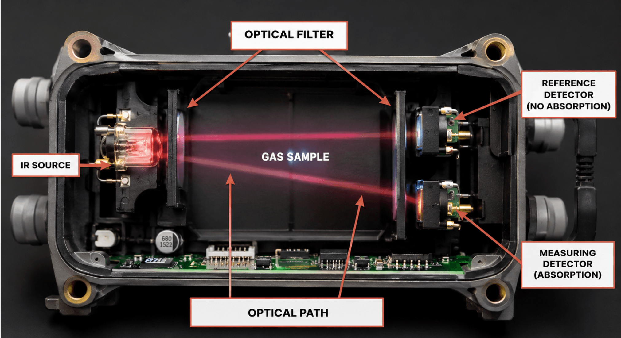
    Infrared gas detection, whether point-type NDIR or open-path, works on a simple optical principle: a beam of infrared light passes through a sample of air, and target gases (typically hydrocarbons or CO₂) absorb specific IR wavelengths.

    The detector compares the energy received at the measurement wavelength with that at a reference wavelength that the target gas doesn’t absorb. The difference tells the instrument how much gas is present.

    That optical path is the system’s greatest strength and its greatest vulnerability. Anything that interferes with light transmission, such as dust, oil film, ice, or water droplets, changes the amount of IR energy reaching the receiver. Condensation is uniquely troublesome because

    Water absorbs infrared energy broadly

    Liquid water and water vapor absorb across large portions of the IR spectrum, including regions near common hydrocarbon measurement bands (around 3.3 µm) and CO₂ bands (around 4.26 µm).

    Droplets scatter light

    Even where water doesn’t absorb strongly, condensed droplets on a lens or mirror scatter the beam, reducing signal at both the measurement and reference wavelengths.

    It forms fast and disappears without a trace

    A detector can fog up at 3 a.m., throw a fault, and be perfectly dry by the time a technician arrives at 9 a.m., which is why condensation problems are so often misdiagnosed.

    What Actually Happens When Condensation Forms on IR Optics

    The effect depends on where the water forms and how the detector’s compensation system handles it.

    Beam block and low-signal faults

    The most common symptom. When enough water accumulates on the optical windows, mirrors, or retroreflector (in open-path systems), total IR energy drops below the detector’s minimum threshold.

    Well-designed instruments respond with a beam block or “low signal” fault rather than a gas reading; the dual-wavelength design recognizes that both channels dropped, which gas absorption wouldn’t cause.

    This is the fail-safe outcome, but it still means your detector is offline. In a facility relying on that point for permit-to-work or ESD logic, a beam block at dawn every day is an operational problem, not just an annoyance.

    False or unstable gas readings

    Less common but more dangerous territory. If condensation affects the measurement and reference wavelengths unevenly, for example, a thin water film with dissolved contaminants or partial fogging on one optical element, the ratio between channels shifts. Depending on the instrument, this can produce the following:

    • Drifting baseline readings (a few % LEL that comes and goes with humidity)
    • Negative readings after the condensation clears
    • Reduced sensitivity: the detector still responds to gas, but under-reads

    Modern detectors from major manufacturers compensate well for uniform attenuation, but no compensation scheme is perfect against non-uniform films or droplets sitting directly in the beam path.

    Long-term optical degradation

    Repeated condensation cycles leave behind residue. Water evaporates; dissolved salts, dust, and process contaminants don’t.

    Over months, this builds a haze on optical surfaces that permanently reduces signal margin. In coastal or marine environments, salt-laden condensation is especially aggressive.

    It’s hygroscopic, so it pulls moisture back onto the optics even in conditions where clean surfaces would stay dry.

    Water ingress and electronics damage

    Condensation isn’t only an optical problem. If it forms inside the enclosure, usually because a gland wasn’t sealed properly or a breather drain was omitted, you get corrosion on PCBs, connector failures, and erratic behavior that looks nothing like a moisture issue. Internal condensation is a killer of otherwise healthy detectors.

    When and Where Condensation Forms

    Condensation appears whenever a surface falls below the dew point of the surrounding air. In gas detection installations, the classic triggers are the following.

    ScenarioWhy It Causes CondensationTypical Symptom
    Day/night temperature swingsThe detector housing cools overnight below the dew point of humid airBeam block faults in early morning that self-clear
    Cooling towers, scrubbers, steam vents nearbyLocally saturated air contacts cooler detector opticsChronic fogging, frequent cleaning needed
    Air-conditioned enclosures venting near detectorsA cold detector surface meets warm humid outdoor airFaults during hot, humid afternoons
    Coastal/tropical climatesSustained high humidity, salt aerosolsOptical haze, corrosion, recurring faults
    Washdown areas (food, pharma)Direct water spray plus high ambient humidityBeam blocks during and after cleaning cycles
    Rapid weather fronts / rain after heatSudden dew point rise over cool equipmentMultiple detectors faulting simultaneously

    That last row is worth noting: if several IR detectors across a site fault at the same time after a weather change, condensation is almost always the cause; real gas releases don’t behave that way.

    Open-Path vs. Point IR Detectors: Different Vulnerabilities

    Open-path infrared (OPIR) systems send a beam across tens or hundreds of meters between a transmitter and receiver (or retroreflector).

    They have more exposed optical surfaces and are also affected by fog, rain, and mist in the beam path itself, not just on the optics.

    Heavy fog can attenuate the beam enough to trigger beam block even with perfectly clean windows.

    Good OPIR designs distinguish between gradual obscuration (dirty optics maintenance warning) and total block (fault), but condensation sits awkwardly between the two.

    Point IR (NDIR) detectors have a short internal optical path protected by a weather baffle and hydrophobic filter.

    They’re far more tolerant of ambient fog, but the small measurement cavity means even a little condensation on the internal mirror or windows has an outsized effect.

    Point IR detectors mounted in cold spots on uninsulated steel near grade, for example, are frequent offenders.

    If you’re still deciding between architectures for a humid site, this trade-off matters as much as coverage geometry. (See our guide on fixed vs. portable and point vs. open-path detection strategies for the full comparison.)

    How Manufacturers Fight Condensation

    Modern IR detectors include several defenses worth understanding, because they affect both product selection and installation:

    Heated optics

    The most effective measure. A small heater keeps optical windows and mirrors a few degrees above ambient, so surfaces stay above dew point.

    Nearly all serious fixed-point IR and OPIR detectors for outdoor use include this; verify it’s specified and, critically, that the detector is actually powered continuously so the heater works. Detectors powered down overnight lose this protection exactly when they need it most.

    Hydrophobic coatings and baffles

    Optical windows treated with hydrophobic coatings shed water as beads rather than films. Weather baffles and sintered or membrane filters keep bulk water spray out while allowing gas diffusion.

    These help, but coatings degrade; never wipe optics with abrasive materials or aggressive solvents during cleaning.

    Dual-wavelength compensation

    As described above, the reference channel lets the instrument ignore attenuation that affects both wavelengths equally.

    This is why IR detectors handle gradual dirt accumulation gracefully and why the technology is inherently more condensation-tolerant than older single-beam designs.

    Enclosure breathers and drains

    For the internal condensation problem, certified breather drains allow pressure equalization and let accumulated moisture escape without compromising the Ex rating.

    If your detectors or junction boxes in humid areas don’t have them, that’s a retrofit worth budgeting.

    Field-Proven Prevention Practices

    From an installation and maintenance standpoint, these are the measures that actually reduce condensation callouts:

    Mind the mounting location

    Avoid mounting detectors directly downwind of cooling towers, steam traps, or scrubber exhausts. A relocation of two or three meters often eliminates chronic fogging.

    Keep detectors continuously powered

    Optics heaters only work when energized. Sites that de-energize field instrumentation during shutdowns often see a wave of beam blocks on restart.

    Orient correctly

    Follow the manufacturer’s orientation requirements (usually horizontal, weather baffle down). Incorrect orientation lets water pool against optical surfaces instead of draining.

    Use sunshades/weather shields

    They reduce radiative cooling at night, a major driver of below-dew-point surfaces as well as daytime solar heating.

    Seal glands and fit breather drains

    Internal condensation is an installation-quality problem. Every unused entry plugged, every gland torqued, and a breather drained at the low point.

    Clean optics on a schedule, correctly

    Use the manufacturer-approved cloth and cleaner. In salty or dusty environments, shorten the interval.

    Log the received signal strength (most detectors report it), and trend it. A slow decline tells you cleaning frequency needs to increase before faults start.

    Bump test after cleaning

    Cleaning optics changes the optical baseline on some instruments. A quick functional check confirms the detector still responds correctly. Our calibration and bump testing guide covers the procedure in detail.

      Condensation vs. Real Gas: How to Tell the Difference

      When investigating an event, these patterns point to condensation rather than gas:

      • A fault or reading occurred in early morning or immediately after a weather change
      • Multiple detectors in different process areas alarmed or faulted simultaneously
      • The instrument logged a beam block / low signal fault rather than a gas concentration
      • The event self-cleared as ambient temperature rose
      • No corroborating reading from nearby catalytic bead, electrochemical, or portable detectors

      None of these justify ignoring an alarm; always respond per procedure, but they should drive the root-cause investigation toward environmental factors before anyone starts hunting for a phantom leak.

      FAQ

      Can condensation cause a false gas alarm on an infrared detector?

      It’s uncommon but possible. Uniform fogging typically causes a beam block fault, not a gas reading, thanks to dual-wavelength compensation.

      However, non-uniform water films or contaminated droplets can unbalance the measurement and reference channels enough to produce erratic or false readings on some instruments.

      Why does my IR gas detector fault every morning?

      Overnight radiative cooling drops the detector’s optical surfaces below the dew point, and condensation forms until the sun warms things up.

      Check that the detector is continuously powered (so its optics heater works), fit a weather shield, and verify correct mounting orientation.

      Does humidity alone affect infrared gas detectors?

      Water vapor has some IR absorption near common measurement bands, but modern detectors are designed and compensated for the full 0–100% RH range.

      Problems begin when vapor becomes liquid; condensing humidity, not high humidity itself, is the real enemy.

      Are catalytic bead detectors better than IR in humid environments?

      Not generally. Catalytic sensors have their own moisture issues (sinter blockage, thermal shock from water spray) plus vulnerabilities IR doesn’t share, like catalyst poisoning. IR with heated optics is usually the better choice for humid sites; the key is proper installation.

      How do I clean condensation residue off IR detector optics?

      Use only the lint-free materials and cleaning solution specified by the manufacturer — typically a mild soap solution or isopropyl alcohol on approved surfaces.

      Never use abrasives or strong solvents, which damage hydrophobic coatings. Verify signal strength and bump test after cleaning.

      Can an NDIR Sensor Detect Hydrogen?

      No, an NDIR sensor cannot detect hydrogen, and it never will. This isn’t a limitation of current technology or something manufacturers will eventually engineer around. It’s a hard boundary set by molecular physics.

      I’ve spent years commissioning gas detection systems in industrial facilities, and this question comes up constantly, especially now that hydrogen projects are multiplying across energy, transport, and battery storage.

      Engineers see NDIR performing brilliantly on methane and CO₂ and reasonably assume it can handle hydrogen too.

      It can’t, and specifying the wrong sensor technology for a hydrogen application is a mistake that can have serious safety consequences.

      Let’s break down exactly why NDIR is blind to hydrogen and which technologies you should use instead.

      How NDIR Sensors Work (A 60-Second Refresher)

      NDIR stands for non-dispersive infrared. The operating principle is elegant in its simplicity:

      1. An infrared source emits broadband IR light through a sample chamber containing the ambient gas.
      2. Target gas molecules in the chamber absorb IR energy at specific wavelengths unique to that gas (methane absorbs strongly around 3.3 µm, CO₂ around 4.26 µm).
      3. An optical filter isolates the wavelength of interest, and a detector measures how much IR energy made it through.
      4. More target gas in the chamber = more absorption = less energy reaching the detector. The electronics convert that attenuation into a concentration reading.

      The entire technology depends on one thing: the target gas must absorb infrared radiation. And that’s precisely where hydrogen fails the entry requirement.

      Why Hydrogen Is Invisible to Infrared

      For a molecule to absorb infrared radiation, its vibration or rotation must produce a change in dipole moment, an asymmetry in how electrical charge is distributed across the molecule as it moves.

      Hydrogen (H₂) is a homonuclear diatomic molecule: two identical hydrogen atoms sharing electrons perfectly symmetrically.

      When an H₂ molecule vibrates, the charge distribution stays symmetric. There is no dipole moment, no change in dipole moment, and therefore no IR absorption at any wavelength an NDIR sensor can use.

      This is the same reason NDIR can’t detect:

      • Oxygen (O₂), homonuclear diatomic
      • Nitrogen (N₂), homonuclear diatomic
      • Chlorine (Cl₂), homonuclear diatomic
      • Helium and argon, monatomic, no molecular vibration at all

      Compare that with CO₂ or methane. These molecules have asymmetric vibration modes that create strong dipole changes, which is why they absorb IR so strongly and why NDIR is the gold standard for detecting them.

      No filter, no wavelength selection, and no clever signal processing changes this. If the gas doesn’t interact with infrared light, an infrared sensor has nothing to measure.

      What This Means in the Field

      I’ve seen this misunderstanding cause real specification errors. A common one: a facility installs IR-based combustible gas detectors (calibrated for methane or propane) in an area that also has hydrogen risk, battery charging rooms, electrolyzer skids, and hydrogen-cooled generators.

      The IR detectors work perfectly for hydrocarbons and give the team a false sense of coverage. Meanwhile, a hydrogen leak in the same space would pass through completely undetected.

      If your hazard assessment includes hydrogen, an infrared point or open-path detector does not count toward your detection coverage for that gas. Full stop.

      Sensor Technologies That DO Detect Hydrogen

      Here are the technologies that actually work for H₂, and where each one fits.

      Catalytic Bead (Pellistor) Sensors

      The workhorse for combustible gas detection, including hydrogen. A heated catalytic element oxidizes the flammable gas, raising the bead’s temperature and changing its resistance.

      Hydrogen oxidizes readily, so catalytic sensors respond well to it, typically reported in % LEL (hydrogen’s LEL is 4% by volume in air).

      Strengths

      It’s proven, affordable, and responds to virtually all flammables.

      Limitations

      It requires oxygen to operate, can be poisoned by silicones and sulfur compounds, and needs regular bump testing and calibration, ideally calibrated on hydrogen itself, since correction factors from methane calibration introduce error.

      Electrochemical Hydrogen Sensors

      These use an electrochemical cell where hydrogen oxidizes at a sensing electrode, generating a current proportional to concentration.

      They’re the go-to for low-level (ppm-range) hydrogen monitoring, think battery rooms, hydrogen leak detection around process equipment, and medical or laboratory settings.

      Strengths

      Excellent sensitivity at ppm levels, low power, compact.

      Limitations

      Finite cell life (typically 2–3 years), cross-sensitivity to CO and other gases, and temperature and humidity effects.

      Thermal Conductivity (TC) Sensors

      Hydrogen has extremely high thermal conductivity, roughly seven times that of air. TC sensors exploit this by measuring how quickly the surrounding gas carries heat away from a heated element.

      Strengths

      Works without oxygen, no catalyst to poison, handles very high concentrations (0–100% volume), and has a fast response.

      Limitations

      Poor sensitivity at low concentrations; best suited for high-range measurement like inerting operations, hydrogen purity monitoring, and generator cooling systems.

      Metal Oxide Semiconductor (MOS) Sensors

      A heated metal oxide film changes resistance when reducing gases like hydrogen adsorb onto its surface.

      Strengths

      Very sensitive, long life, low cost.

      Limitations

      Broad cross-sensitivity (responds to many gases, not just H₂), drift, and humidity dependence are better for leak indication than precise measurement.

      MEMS and Solid-State Hydrogen-Specific Sensors

      A newer generation of sensors includes palladium-based and MEMS thermal conductivity designs built specifically for the hydrogen economy: fuel cell vehicles, refueling stations, and electrolyzers.

      These are increasingly common where hydrogen selectivity and fast response (per standards like ISO 26142) are required.

      Hydrogen Detection Technology Comparison

      TechnologyDetects H2?Typical RangeNeeds O2?Best For
      NDIR (infrared)❌ NoN/ANoCO₂, methane, hydrocarbons, never H₂
      Catalytic bead✅ Yes0–100% LELYesGeneral combustible/LEL monitoring
      Electrochemical✅ Yesppm rangeNoBattery rooms, low-level leak detection
      Thermal conductivity✅ Yes% volume to 100%NoHigh concentrations, purity, inerting
      MOS / semiconductor✅ Yesppm–%NoLow-cost leak indication
      MEMS / Pd-based solid state✅ YesVariesNoFuel cells, refueling stations, H₂ economy

      Choosing the Right Approach

      From a system design standpoint, here’s how I approach hydrogen detection specification:

      Define the measurement goal first

      Are you protecting against explosion risk (measure % LEL), monitoring for early leaks (ppm), or verifying gas purity (% volume? Each points to a different technology.

      For flammability protection

      Catalytic bead detectors calibrated on hydrogen remain the most common choice in fixed systems, often paired with thermal conductivity elements for full-range coverage.

      For battery rooms and UPS installations

      Electrochemical ppm-level sensors provide early warning long before concentrations approach the 4% LEL, usually with alarms at 1% and 2% volume (25% and 50% LEL).

      Mind the placement

      Hydrogen is the lightest gas that exists; it rises fast and accumulates at ceiling level, in roof peaks, and under canopies. Hydrogen detectors mount high, unlike propane or LPG sensors that mount low. Ventilation patterns matter enormously.

      Never rely on odor

      Hydrogen is colorless and completely odorless, and unlike natural gas, it’s typically not odorized because odorants poison fuel cells. Instrumented detection is the only reliable safeguard.

      Frequently Asked Questions

      Can an NDIR sensor detect hydrogen at any concentration?

      No. The limitation is physical, not one of sensitivity. Hydrogen doesn’t absorb infrared radiation at all because it’s a symmetric homonuclear molecule with no dipole moment. No concentration of hydrogen produces any NDIR signal.

      Why does NDIR work for methane but not hydrogen?

      Methane (CH₄) has asymmetric vibration modes that change its dipole moment, producing strong IR absorption around 3.3 µm. Hydrogen’s vibration is perfectly symmetric, so it produces no dipole change and no IR absorption.

      What is the best sensor for detecting hydrogen gas?

      It depends on the range you need. Electrochemical sensors excel at ppm-level leak detection, catalytic bead sensors are the standard for % LEL flammability monitoring, and thermal conductivity sensors handle high-percentage concentrations. Many fixed hydrogen detection systems combine technologies.

      Can infrared open-path detectors see a hydrogen cloud?

      No. Open-path IR detectors have the same physical limitation as point NDIR sensors. For hydrogen, alternatives include ultrasonic leak detectors (which “hear” the acoustic signature of a pressurized leak) combined with catalytic or electrochemical point detection.

      Does hydrogen affect NDIR sensors calibrated for other gases?

      Hydrogen won’t produce a direct reading, but at very high concentrations it can slightly alter the thermal and optical properties of the sample chamber. In practice, treat NDIR as completely non-responsive to hydrogen for safety purposes.

      Where should hydrogen detectors be mounted?

      High, at or near ceiling level, above potential leak sources. Hydrogen is about 14 times lighter than air and rises rapidly, collecting at the highest points of an enclosure.

      The Bottom Line

      An NDIR sensor cannot detect hydrogen today, not with better engineering, not ever. Hydrogen’s symmetric molecular structure makes it fundamentally invisible to infrared absorption measurement.

      If hydrogen appears anywhere in your hazard assessment, your detection layer needs catalytic bead, electrochemical, thermal conductivity, or hydrogen-specific solid-state sensors selected according to the concentration range that matters for your application.

      Infrared detection is superb technology for the gases it can see. Knowing which gases it can’t see is just as important, and hydrogen tops that list.

      Why NDIR Technology Can Extend Portable Detector Battery Life

      If you’ve ever pulled a portable multi-gas detector off the charging dock only to find it dead by the end of a 12-hour shift, there’s a good chance the culprit isn’t your battery.

      It’s your LEL sensor. NDIR technology (non-dispersive infrared) has quietly become one of the most effective ways to extend portable detector battery life, in some cases stretching runtime from a single shift to several weeks between charges.

      I work with gas detection systems every day as an industrial safety engineer, and the shift from catalytic bead to infrared LEL sensing is one of the most practical upgrades I recommend to plant safety managers.

      In this article, I’ll explain exactly why NDIR sensors sip power while catalytic bead sensors gulp it, what real-world runtime numbers look like, and when the switch makes sense for your fleet.

      The Battery Problem in Portable Gas Detection

      Most portable multi-gas detectors monitor four channels: oxygen, carbon monoxide, hydrogen sulfide, and combustible gases (LEL). The first three use electrochemical cells, which are remarkably efficient.

      They generate a small current from the chemical reaction with the target gas and draw almost nothing from the battery.

      The combustible gas channel is different. For decades, the default sensing element has been the catalytic bead (pellistor), and it is by far the hungriest component in the instrument.

      In a typical four-gas portable, the catalytic LEL sensor can account for well over half of total power consumption.

      That’s why a detector rated for 12–14 hours of runtime with a catalytic bead can suddenly run for weeks when the LEL channel is swapped for an infrared sensor.

      Understanding why requires a quick look at how each technology actually detects gas.

      How Catalytic Bead Sensors Burn Through Power

      A catalytic bead sensor works by literally burning the target gas. Inside the sensor are two small ceramic beads wound with platinum wire:

      • The active bead is coated with a catalyst that oxidizes (combusts) flammable gas on its surface.
      • The reference bead is inert and compensates for ambient temperature and humidity.

      For combustion to occur on the active bead, it must be heated continuously to roughly 400–500°C.

      That heating current never stops while the instrument is on, whether gas is present or not. Depending on the design, a pellistor pair draws somewhere in the range of 100–300 milliwatts, constantly, for the entire shift.

      Think of it like leaving a tiny stove burner on inside your detector for 12 hours straight. It works, and it’s a proven technology, but it’s thermodynamically expensive.

      Catalytic beads carry two other operational costs worth mentioning, because they compound the battery issue:

      1. They require oxygen to combust the gas, so they can under-read in inert or oxygen-deficient atmospheres, a real concern in confined space entry work.
      2. They can be poisoned by silicones, sulfur compounds, and lead, which degrades sensitivity silently until a bump test catches it.

      How NDIR Technology Works And Why It’s So Efficient

      NDIR technology takes a completely different approach: instead of burning the gas, it shines light through it.

      Hydrocarbon molecules absorb infrared light at specific wavelengths. Most combustible gases absorb strongly around 3.3 µm, where the carbon-hydrogen bond resonates. An NDIR sensor contains:

      • An infrared source (a micro-lamp, MEMS emitter, or IR LED)
      • An optical path or chamber where ambient gas diffuses in
      • Two detectors: one at the active wavelength (3.3 µm for hydrocarbons) and one at a reference wavelength (typically ~3.9 µm) where nothing absorbs

      When combustible gas enters the chamber, it absorbs some of the IR energy at the active wavelength.

      The instrument compares the active and reference signals and calculates gas concentration from the difference, a principle known as the Beer–Lambert law.

      Here’s the key to the power savings: the IR source doesn’t need to run continuously. It can be pulsed, flashed on for milliseconds, then switched off several times per second.

      Between pulses, the sensor draws almost nothing. Modern designs using IR LEDs or MEMS emitters push efficiency even further, with average power draw an order of magnitude (or more) below a heated pellistor.

      There’s no bead to keep at combustion temperature. No continuous heating current. Just brief, scheduled flashes of light.

      Catalytic Bead vs NDIR: Power and Performance Compared

      CharacteristicCatalytic Bead (Pellistor)NDIR Infrared
      Detection principleCombustion on heated catalystIR absorption at ~3.3 µm
      Operating temperatureBead heated to ~400–500°C continuouslyAmbient, pulsed IR source
      Typical power drawHigh, continuous heating currentLow, pulsed source, minimal average draw
      Impact on portable runtimeOften limits detector to ~1 shift per chargeEnables weeks between charges
      Oxygen requirementYes (needs O₂ to combust gas)No, works in inert atmospheres
      Poisoning risk (silicones, H₂S, lead)YesNo
      Fail-safe behaviorCan fail undetected (poisoned bead reads zero)Optical failure is self-evident (fault flagged)
      Detects hydrogenYesNo (H₂ has no C–H bond to absorb IR)
      Typical sensor life2–5 years, less if poisoned5+ years
      Sensor costLower upfrontHigher upfront

      Real-World Battery Life: What to Expect

      Numbers vary by manufacturer and configuration, but the pattern is consistent across the industry:

      • A four-gas portable with a catalytic LEL sensor typically delivers 12–18 hours of continuous runtime, enough for one long shift, then back on the dock.
      • The same instrument platform with an IR LEL sensor commonly delivers one to two months of runtime on a charge, because the dominant power load is gone.

      That’s not a marginal improvement; it changes how a fleet operates. Charging docks become less of a bottleneck, workers stop fighting over the “good” units, and a detector left in a truck over a long weekend still turns on Monday morning.

      The efficiency gain also enables entirely new form factors. Serviceable multi-year detectors with IR LEL channels, devices that run for years with minimal intervention, are only practical because NDIR removed the pellistor’s constant heating load from the power budget.

      When NDIR Is the Right Choice (And When It Isn’t)

      Based on my field experience, NDIR LEL sensors are the stronger choice when

      • Battery runtime is a pain point: long shifts, remote sites, limited charging infrastructure
      • You work in inert or low-oxygen atmospheres: nitrogen-purged vessels, confined spaces where catalytic beads under-read
      • Sensor poisoning is a known problem: facilities with silicone lubricants, sulfur compounds, or leaded environments
      • Total cost of ownership matters more than purchase price: longer sensor life and fewer failed bump tests offset the higher upfront cost

      Catalytic bead sensors still earn their place when:

      Hydrogen detection is required

      This is the big one. Hydrogen has no carbon-hydrogen bond, so it’s invisible to standard 3.3 µm NDIR sensors.

      If H₂ is in your hazard assessment, you need a catalytic bead, an electrochemical H₂ sensor, or another technology on that channel.

      Budget

      Budget constraints dominate, and the application is a well-ventilated, poison-free environment with reliable daily charging.

      Broad

      Broad, non-selective flammable response is desired; pellistors respond to nearly any combustible gas, while IR response varies by hydrocarbon.

      Practical Tips for Switching Your Fleet to IR LEL

      Audit your hazard assessment first

      Confirm hydrogen and other non-hydrocarbon flammables (like carbon disulfide) aren’t in scope before dropping the catalytic bead.

      Check calibration gas compatibility

      IR sensors are typically calibrated on methane or propane, and cross-sensitivity factors differ from pellistors. Update your calibration procedures accordingly.

      Don’t skip bump testing

      Lower poisoning risk doesn’t mean zero maintenance — daily bump tests remain best practice regardless of sensor technology.

      Recalculate your charging logistics

      Fleets often over-provision docks for single-shift runtime. Moving to IR LEL may let you consolidate charging stations and spare units.

      Pilot before you commit

      Run a handful of IR-equipped units alongside your catalytic fleet for a quarter and compare downtime, failed bump tests, and battery complaints.

        Frequently Asked Questions

        Does NDIR technology really extend portable gas detector battery life?

        Yes. The catalytic bead LEL sensor is typically the largest power consumer in a portable multi-gas detector because its bead must be heated continuously to around 400–500°C.

        NDIR sensors replace that constant heating load with a pulsed infrared source, reducing average power draw dramatically, often extending runtime from a single shift to several weeks.

        Can NDIR sensors detect hydrogen?

        No. Standard NDIR sensors detect gases by their infrared absorption at the carbon-hydrogen bond wavelength (~3.3 µm).

        Hydrogen contains no carbon and doesn’t absorb at this wavelength, so it’s invisible to hydrocarbon NDIR sensors. Sites with hydrogen hazards should retain catalytic beads or dedicated H₂ sensing on that channel.

        Do NDIR sensors work in oxygen-deficient atmospheres?

        Yes, and this is a major safety advantage. Catalytic bead sensors need oxygen to combust the target gas and can dangerously under-read in inert or oxygen-depleted environments.

        NDIR sensors measure light absorption, which works identically with or without oxygen present, making them well suited to confined space and inerted-vessel work.

        Are NDIR sensors immune to poisoning?

        Effectively, yes. The silicones, sulfur compounds, and lead that permanently degrade catalytic beads have no effect on optical IR measurement.

        NDIR sensors also tend to be fail-safe: if the optical path is blocked or the source fails, the instrument flags a fault rather than silently reading zero.

        Why do NDIR sensors cost more than catalytic beads?

        The optical components: IR source, filters, and dual detector cost more to manufacture than a pellistor pair.

        However, longer sensor life (often 5+ years), immunity to poisoning, and reduced charging infrastructure usually deliver a lower total cost of ownership over the life of the instrument.

        The Bottom Line

        Portable detector battery life isn’t really a battery problem; it’s a sensor power problem. Catalytic bead LEL sensors spend the entire shift running a miniature heater at combustion temperature, while NDIR technology measures the same hazard with brief pulses of infrared light.

        The result is runtime measured in weeks instead of hours, plus meaningful safety gains in inert atmospheres and poison-prone environments.

        If hydrogen isn’t part of your hazard profile, moving your fleet’s LEL channel to infrared is one of the highest-impact, lowest-risk upgrades available in portable gas detection today.

        How to Test an Oxygen Sensor: A Step-by-Step Guide From the Field

        If your gas detector’s oxygen sensor fails when you need it most, the consequences can be fatal. Oxygen-deficient atmospheres are among the leading causes of confined space deaths, and in nearly every incident report I’ve reviewed, the warning signs were there long before the alarm failed to sound.

        I’m an industrial automation engineer specializing in gas detection and safety systems, and testing oxygen sensors is something I’ve done hundreds of times across refineries, water treatment plants, and manufacturing facilities.

        In this guide, I’ll show you exactly how to test an oxygen sensor the way it’s done in professional settings no guesswork, no shortcuts.

        How to Test an Oxygen Sensor

        To test an oxygen sensor, first verify it reads 20.9% vol in fresh air, then perform a bump test by applying a known concentration of test gas (typically 18.0% O₂ in nitrogen) and confirming the low-oxygen alarm activates.

        If the reading drifts outside ±0.5% of the applied gas concentration, perform a full calibration. If the sensor fails to calibrate, replace it.

        Let’s break each step down in detail.

        Why Testing Your Oxygen Sensor Matters

        Electrochemical oxygen sensors, the type found in virtually all portable gas monitors, are consumable components.

        They rely on a chemical reaction (typically lead oxidation or, in newer lead-free designs, an oxygen pump cell) that depletes over time whether you use the instrument or not.

        A typical electrochemical O₂ sensor lasts 18 to 24 months. Newer long-life sensors can reach 5 years. But here’s the critical point: a dying oxygen sensor often fails gradually, not suddenly. It may still show a plausible reading while responding too slowly or not at all to a real oxygen deficiency.

        That’s why OSHA guidance and manufacturers like Honeywell, Dräger, and Industrial Scientific all recommend the same thing: bump test before each day’s use and calibrate on a regular schedule (typically monthly or per your site’s safety program).

        Fresh Air Reading: The First Check

        Before anything else, confirm your baseline.

        1. Take the detector to clean, fresh air outdoors, away from vehicle exhaust, exhaust vents, or any process area.
        2. Power on the instrument and let it complete its startup sequence and warm-up (usually 30–60 seconds).
        3. Check the O₂ reading. In fresh air at normal atmospheric pressure, it should display 20.9% vol.

        If the reading shows something like 20.4% or 21.3%, the sensor has drifted. A small drift is normal over weeks of use and is corrected with a fresh air calibration (often called “zeroing” or “fresh air setup” on instruments like the Honeywell BW Solo or BW Clip).

        If the reading is wildly off, say, 17% in fresh air, skip straight to a full calibration, and if that fails, replace the sensor.

        Pro tip from the field

        Never perform a fresh air calibration indoors in a plant environment. I’ve seen technicians “zero” a detector in a compressor room where the actual O₂ level was slightly depressed, which shifted the entire measurement scale and masked a real hazard later in that shift.

        How to Bump Test an Oxygen Sensor (Daily Check)

        A bump test is a quick functional check: you expose the sensor to test gas and verify the alarm responds. It takes under a minute, and it’s the single most important habit in gas detection.

        What You’ll Need

        • Your gas detector with the O₂ sensor installed
        • A cylinder of certified test gas for oxygen sensors; this is typically 18.0% O₂ balanced in nitrogen (often part of a multi-gas mix that also contains CO, H₂S, and methane)
        • A fixed-flow regulator (0.5 LPM is standard)
        • Calibration tubing and the correct calibration cap/adapter for your instrument

        Read more about bump tests in gas detection.

        Step-by-Step Bump Test Procedure

        1. Check the test gas expiration date. Expired gas gives unreliable results. Oxygen mixes are stable, but if your mix includes reactive gases like H₂S, shelf life matters.
        2. Power on the detector in fresh air and confirm the 20.9% baseline.
        3. Attach the calibration cap to the detector and connect the tubing to the regulator.
        4. Open the regulator and let the gas flow over the sensor.
        5. Watch the display. The O₂ reading should drop from 20.9% toward 18.0% within about 30 seconds. Most sensors reach T90 (90% of final reading) in 15 seconds or less when healthy.
        6. Confirm the low-oxygen alarm activates. The default low alarm is 19.5% vol (the OSHA-defined oxygen-deficient threshold), so the reading passing below that point must trigger audible, visual, and vibration alarms.
        7. Remove the gas and confirm the reading recovers to 20.9% within a minute or so.

        Pass criteria

        The alarm activated, and the reading settled within ±0.5% vol of the test gas concentration (i.e., between 17.5% and 18.5% for an 18.0% mix).

        Fail criteria

        No alarm, sluggish response (taking 60+ seconds to move), or a final reading outside tolerance. A failed bump test means the instrument goes out of service until it passes a full calibration.

        Bump Test vs. Calibration: What’s the Difference?

        Bump TestFull Calibration
        PurposeVerify sensor responds, and alarms workAdjust sensor accuracy to a known standard
        FrequencyBefore each day’s useMonthly (or per manufacturer/site policy)
        Duration30–60 seconds2–5 minutes
        Adjusts readings?No, pass/fail onlyYes, resets span and zero points
        Gas requiredCertified test gasCertified calibration gas
        If it failsPerform full calibrationReplace the sensor

        How to Calibrate an Oxygen Sensor (Full Test)

        If the bump test fails, or your calibration interval is due, perform a full calibration. The exact menu steps vary by instrument, but the logic is universal.

        Fresh air calibration (zero/span for O₂).

        Oxygen sensors are unusual: fresh air at 20.9% actually serves as the span point for many instruments, since it’s a known, stable concentration. Enter the calibration menu and run the fresh air setup in clean outdoor air.

        Apply calibration gas

        Connect your 18.0% O₂ (or the concentration your manufacturer specifies) and let the instrument sample it. Docking stations like the Honeywell IntelliDoX or Industrial Scientific DSX automate this entire sequence.

        Let the instrument adjust

        The detector compares the sensor’s raw output against the known gas value and corrects its internal scaling.

        Verify

        After calibration, the sensor should read the applied gas concentration within tolerance and return cleanly to 20.9% in fresh air.

        If calibration fails or the sensor can’t reach span

        The electrochemical cell is depleted. There is no fixing a dead O₂ sensor; replacement is the only option.

        Most portable monitors make this a simple swap; just remember the new sensor needs a stabilization period (often several hours to overnight) before its first calibration.

        5 Signs Your Oxygen Sensor Is Failing

        Catch a dying sensor before it fails a bump test.

        1. Drifting fresh air readings: you find yourself re-zeroing more often than usual.
        2. Slow response time: the reading crawls toward the test gas value instead of dropping quickly.
        3. Failure to recover after removing test gas: the sensor takes minutes to climb back to 20.9%.
        4. Erratic or jumpy readings: the display fluctuates with no atmospheric change, often a sign of electrolyte depletion or a damaged membrane.
        5. If the sensor is past its rated service life (check the manufacture date printed on the sensor body), replace it proactively. Don’t wait for the failure.

        Common Mistakes to Avoid

        Zeroing in contaminated air

        Always use genuinely fresh outdoor air for the fresh air setup.

        Using expired or wrong test gas

        Pure nitrogen (0% O₂) can be used to check that the sensor responds downward, but it doesn’t verify accuracy at the alarm point the way an 18.0% mix does.

        Skipping the bump test because “it passed yesterday.”

        Sensors can be poisoned or blocked overnight; dropped instruments, blocked sensor ports, and temperature shock are all real-world failure causes I’ve encountered.

        Blowing exhaled breath on the sensor as a “test.”

        Your breath is roughly 16% O₂, so the reading will drop, but this is not a controlled test; it doesn’t verify accuracy and introduces moisture into the sensor. Some manufacturers explicitly warn against it.

        Ignoring altitude and pressure

        O₂ sensors measure partial pressure. At high altitude, readings shift; calibrate at the altitude where the instrument will be used.

        Frequently Asked Questions

        What should an oxygen sensor read in normal air?

        20.9% vol. That’s the oxygen concentration of Earth’s atmosphere at sea level, and it’s the universal fresh air baseline for gas detection instruments.

        How often should I test my oxygen sensor?

        Bump test before each day’s use, and perform a full calibration at least monthly or per your manufacturer’s and site safety program’s requirements. High-exposure environments may require more frequent calibration.

        What gas do you use to test an oxygen sensor?

        The standard is a certified mix of 18.0% oxygen balanced in nitrogen, usually supplied as part of a quad-gas cylinder. Pure nitrogen can verify downward response but does not confirm accuracy at the alarm setpoint.

        How long does an oxygen sensor last in a gas detector?

        Standard electrochemical O₂ sensors last 18–24 months. Long-life lead-free O₂ sensors, now common in instruments like the Honeywell BW Solo and MicroClip XL, are rated for up to 5 years.

        Can you recalibrate a failed oxygen sensor?

        No. If a sensor fails calibration, the electrochemical cell is depleted and must be replaced. Calibration corrects drift in a healthy sensor; it cannot restore a dead one.

        At what oxygen level does the alarm go off?

        The default low alarm on most instruments is 19.5% vol, matching OSHA’s definition of an oxygen-deficient atmosphere. The high alarm is typically 23.5% vol., indicating oxygen enrichment is a serious fire hazard.

        Final Thoughts

        Testing an oxygen sensor comes down to three habits: verify 20.9% in fresh air, bump test daily with certified gas, and calibrate on schedule. It costs you a minute at the start of a shift. Skipping it can cost far more.

        How Do You Know When Your Oxygen Sensor Is Bad? 7 Warning Signs Every Worker Should Recognize

        The oxygen sensor is arguably the most important in your gas detector. It’s the one standing between you and an atmosphere that can render you unconscious in seconds without any warning smell, taste, or color. So how do you know when your oxygen sensor is bad?

        How Do You Know When Your Oxygen Sensor Is Bad?

        Your oxygen sensor is bad when it fails a bump test, won’t hold calibration, responds slowly to gas, displays erratic or drifting readings, or has exceeded its expected lifespan (typically 2–3 years for standard electrochemical sensors).

        Any one of these signs means the sensor should be replaced immediately, not “next week” or “after this shift.”

        In my years working with gas detection systems in industrial environments, I’ve seen workers trust monitors with dying O₂ sensors simply because the display still showed a number.

        A number on a screen means nothing if the sensor behind it can no longer do its job. Let’s walk through exactly how oxygen sensors fail, the warning signs to watch for, and what to do about it.

        Why Oxygen Sensors Fail (Even When Nothing Goes Wrong)

        Here’s something that surprises many people: standard electrochemical oxygen sensors are consumable by design.

        Most traditional O₂ sensors use a lead-based electrochemical cell. The sensor works through a controlled oxidation reaction: oxygen diffuses into the cell and reacts with a lead anode, generating a small electrical current proportional to the oxygen concentration.

        Every second the sensor is exposed to air (which is all the time, since we live in a 20.9% oxygen atmosphere), it consumes a little bit of that lead anode.

        When the lead is gone, the sensor is done. No repair, no recharge, no reset. This is why oxygen sensors fail even in detectors that sit unused in a drawer.

        Unlike a catalytic bead LEL sensor that mostly degrades with gas exposure, an O₂ sensor is dying from the day it’s manufactured.

        Typical oxygen sensor lifespans:

        Sensor TypeExpected LifespanNotes
        Standard lead-based electrochemical1–3 yearsConsumed continuously by ambient oxygen
        Long-life / lead-free O₂ sensorsUp to 5 yearsFound in newer monitors: pump-free oxygen-sensing designs
        High heat/humidity environmentsReduced by 20–50%Extreme conditions accelerate electrolyte loss

        If your monitor’s O₂ sensor is past the 2-year mark, treat every warning sign below with extra suspicion.

        7 Signs Your Oxygen Sensor Is Bad

        It Fails a Bump Test

        The bump test is your first and most reliable line of defense. A bump test briefly exposes the sensor to a known concentration of test gas to verify the sensor responds, and the alarms activate.

        For oxygen sensors, the bump test typically uses a gas mixture with a reduced oxygen concentration (often 18% or lower, since O₂ sensors alarm on deficiency).

        If the sensor doesn’t respond, responds too slowly, or fails to trigger the alarm, the sensor is bad full stop.

        A failed bump test isn’t a suggestion to “try again tomorrow.” Take the unit out of service until the sensor is replaced and the monitor passes a full calibration.

        It Won’t Hold Calibration (or Fails Calibration Entirely)

        Calibration adjusts the sensor’s response to match a known gas concentration. A healthy oxygen sensor should calibrate cleanly and hold that calibration between scheduled intervals.

        Warning signs during calibration

        The sensor fails to reach the target reading during span calibration. The monitor displays a calibration fault or “sensor error” code.

        The sensor calibrates successfully but drifts out of spec within days. You find yourself calibrating more and more frequently just to keep the unit usable.

        That last one is the sneaky killer. If your O₂ sensor needed calibration once a month last year and now needs it weekly, the sensing cell is depleting. Frequent recalibration is a symptom, not a solution.

        Slow Response Time (T90 Degradation)

        Sensor manufacturers specify a response time called T90: the time it takes the sensor to reach 90% of its final reading after gas exposure.

        A healthy electrochemical O₂ sensor typically has a T₉₀ under 30 seconds, often closer to 10–15 seconds.

        As the sensing cell degrades, response time stretches. During a bump test or calibration, pay attention to how long the reading takes to move, not just whether it eventually gets there.

        A sensor that takes 60+ seconds to respond might technically pass an automated test, but in a real confined space entry, that lag could be the difference between exiting safely and collapsing at the bottom of a tank.

        Erratic, Jumpy, or Drifting Readings

        In normal ambient air, your oxygen reading should sit steady at 20.9% (or very close to it, depending on altitude and calibration). Watch for:

        Drift the reading slowly wanders, showing 20.4% one hour and 21.3% the next in the same clean air.

        Jumpiness: the display bounces between values with no atmospheric change.

        Stuck readings: the display freezes at 20.9% and never moves, even during a bump test. A stuck “normal” reading is the most dangerous failure mode of all, because everything looks fine.

        Readings That Don’t Match Reality

        If your monitor shows 17% oxygen in a well-ventilated open area or reads 20.9% inside a nitrogen-purged vessel, the sensor has lost its grip on reality.

        Always sanity-check O2 readings against what you know about the environment. Fresh outdoor air is 20.9%. If your monitor disagrees, believe the atmosphere, not the sensor, and pull the unit from service.

        Error Codes and Sensor Fault Warnings

        Modern monitors like the Honeywell BW series, MSA ALTAIR line, and Industrial Scientific Ventis units run continuous sensor diagnostics.

        A “sensor fault,” “sensor missing,” or “negative drift” error on the O₂ channel usually means the electrochemical cell’s output has dropped below the level the instrument can compensate for. Don’t clear the error and keep working; the monitor is telling you the sensor is at the end of its life.

        Physical Damage or Environmental Abuse

        Electrochemical sensors contain liquid electrolyte behind a diffusion membrane. They’re vulnerable to:

        Extreme heat, which accelerates electrolyte evaporation. Very dry environments, which dehydrate the cell. Physical impact that cracks the housing or membrane. Chemical exposure (certain solvents and gases can poison or clog the membrane).

        If a monitor has been dropped, left on a dashboard in the sun, or exposed to a chemical splash, bump test it before the next use even if it’s not on the schedule.

        Bad O2 Sensor vs. Other Problems: A Quick Diagnostic Table

        SymptomLikely Bad SensorOther Possible Cause
        Fails bump test✔ YesExpired calibration gas, blocked gas inlet
        Reads low in fresh air✔ YesNeeds fresh air (zero) calibration, altitude change
        Slow response✔ YesClogged sensor filter, blocked sample line (pumped units)
        Reads 0% or blank✔ Yes (dead cell)Loose sensor connection, board fault
        Frequent recalibration needed✔ YesTemperature swings between cal and use environment
        Erratic readings✔ YesRF interference, moisture in sensor port

        Before condemning a sensor, rule out the cheap fixes: check your calibration gas cylinder’s expiration date and pressure, inspect and replace sensor filters, and confirm sample lines and pumps are clear. But when in doubt, replace the sensor; an O₂ sensor costs far less than an incident report.

        What to Do When Your Oxygen Sensor Is Bad

        Remove the monitor from service immediately

        Tag it so no one else grabs it for a confined space entry.

        Replace the sensor; don’t just recalibrate

        Calibration cannot revive a depleted electrochemical cell.

        Use manufacturer-approved replacement sensors

        Third-party cells may not match the instrument’s compensation algorithms.

        Perform a full calibration after replacement

        Followed by a bump test before returning the unit to service.

        Log the replacement date

        Start the lifespan clock so you can replace it proactively next time instead of reactively.

        How to Extend Oxygen Sensor Life

        You can’t stop a lead-based O₂ sensor from consuming itself, but you can avoid shortening its life: store monitors in moderate temperatures away from direct sunlight, keep sensor filters clean and replaced on schedule, avoid chemical splash and solvent vapor exposure during storage, and follow the manufacturer’s storage humidity recommendations. If sensor replacement costs are adding up across a fleet, consider upgrading to monitors with long-life, lead-free O₂ sensors rated for 4–5 years.

        Frequently Asked Questions

        How long does an oxygen sensor last in a gas detector?

        Standard lead-based electrochemical oxygen sensors last 1–3 years, with 2 years being a realistic planning number.

        Newer lead-free “long-life” O₂ sensors last up to 5 years. Heat, dryness, and rough handling shorten lifespan.

        Can you recalibrate a bad oxygen sensor?

        No. Calibration adjusts the instrument’s interpretation of the sensor’s signal. It cannot restore a depleted or damaged sensing cell. If a sensor fails calibration or won’t hold calibration, replacement is the only fix.

        Why does my oxygen sensor fail even though I rarely use the monitor?

        Because electrochemical O₂ sensors react with ambient oxygen continuously, whether the monitor is powered on or not. The sensor is being consumed even while sitting in storage.

        How often should I bump test my oxygen sensor?

        Best practice and the recommendation of major manufacturers and safety bodies is a bump test before each day’s use.

        At minimum, bump test before any confined space entry or work in a potentially hazardous atmosphere.

        What should my oxygen sensor read in normal air?

        20.9% volume oxygen at sea level. Readings meaningfully above or below that in clean, fresh air indicate a calibration or sensor problem.

        Note that high altitude lowers oxygen partial pressure, which can affect some sensor readings slightly.

        Is a stuck 20.9% reading dangerous?

        Extremely. A sensor frozen at “normal” gives false confidence in an atmosphere that may be oxygen-deficient.

        This is exactly why bump testing matters. It’s the only way to catch a sensor that has quietly stopped responding.

        Final Thoughts

        So, how do you know when your oxygen sensor is bad? It fails a bump test, resists calibration, responds sluggishly, drifts or freezes in clean air, throws sensor faults, or has simply aged past its service life.

        Oxygen sensors are consumables. Plan for replacement the way you plan for battery replacement, and never gamble on a sensor that shows any of the seven warning signs above.

        Your gas detector is only as trustworthy as its weakest sensor. Bump test daily, calibrate on schedule, and when the O₂ sensor gives you a reason to doubt it, replace it without hesitation.

        NDIR vs. Catalytic Bead Sensor: Which Combustible Gas Detection Technology Is Right for You?

        Choosing the wrong combustible gas sensor can leave your team blind to a hazard or drown them in false alarms.

        After years of specifying, commissioning, and troubleshooting gas detection systems in industrial facilities, I can tell you that the NDIR vs catalytic bead sensor decision comes up in almost every portable gas detector selection I’m involved in.

        Both technologies are proven, reliable, and widely deployed. But they work on completely different physical principles, and each has blind spots that can compromise safety if you deploy them in the wrong application.

        In this guide, I’ll break down how each sensor works, where each one excels, where each one fails, and give you a practical decision framework based on real-world field experience.

        NDIR vs. Catalytic Bead Sensor: Which Combustible Gas Detection Technology Is Right for You?

        Catalytic bead sensors are the workhorse of portable gas detection: affordable, versatile, and effective for most everyday combustible gas hazards. They burn the target gas on a heated catalyst and measure the resulting temperature change.

        NDIR (non-dispersive infrared) sensors measure how gas molecules absorb infrared light. They’re immune to sensor poisoning, work without oxygen, and detect heavy hydrocarbons that catalytic sensors miss, but they cost 3–4 times more and cannot detect hydrogen.

        If your hazards vary day to day and include hydrogen, go catalytic. If you work in inert atmospheres, around silicones and sulfur compounds, or with heavy fuel vapors like diesel and jet fuel, NDIR is worth the premium.

        Now let’s dig into why.

        How Catalytic Bead Sensors Work

        A catalytic bead sensor (often called a “pellistor” or catalytic LEL sensor) contains two small beads of ceramic material wound with platinum wire. One bead is coated with a catalyst; the other is inert and serves as a reference.

        When combustible gas reaches the active bead, it oxidizes, essentially burning on the catalyst surface.

        This combustion raises the bead’s temperature, which changes the electrical resistance of the platinum wire.

        The sensor measures the resistance difference between the active and reference beads and converts it into a gas concentration reading, typically expressed as a percentage of the Lower Explosive Limit (%LEL).

        Key Characteristics of Catalytic Bead Sensors

        Because catalytic sensors rely on combustion, they have two fundamental requirements: the target gas must be flammable, and oxygen must be present for oxidation to occur.

        Most catalytic sensors need at least 10–12% oxygen in the atmosphere to read accurately. In oxygen-deficient or inert atmospheres like nitrogen-purged vessels, a catalytic sensor will dangerously under-report gas concentrations.

        The catalyst itself is also the sensor’s Achilles heel. Certain compounds permanently degrade or destroy the catalyst, a phenomenon known as sensor poisoning. Common poisons include the following:

        • Silicones (found in lubricants, sealants, and hydraulic fluids)
        • Sulfur compounds (hydrogen sulfide in high concentrations)
        • Lead compounds
        • Halogenated hydrocarbons (which act as inhibitors)
        • Phosphates and phosphorus-containing substances

        A poisoned catalytic sensor may still power on and appear functional while responding poorly or not at all to gas.

        This is exactly why regular bump testing is non-negotiable for catalytic-based portable monitors. If you’re not bump testing daily, you’re gambling with a sensor that may already be dead.

        How NDIR Sensors Work

        Non-dispersive infrared (NDIR) combustible gas sensing is based on a completely different principle: the absorption of infrared energy by the chemical bonds between dissimilar atoms in a gas molecule.

        Inside an NDIR sensor, an infrared source emits light through an optical path containing the gas sample.

        Hydrocarbon molecules absorb infrared energy at specific, characteristic wavelengths. A detector at the other end of the optical path measures how much infrared light was absorbed at the target wavelength, and that absorption is proportional to the gas concentration.

        Because the measurement is optical rather than chemical, nothing is consumed or burned. The gas simply passes through a beam of light.

        Key Characteristics of NDIR Sensors

        The optical measurement principle gives NDIR sensors three major advantages.

        Immunity to poisoning

        There’s no catalyst to degrade. Silicones, sulfur compounds, and lead have no effect on the sensor’s ability to detect gas.

        No oxygen requirement

        Since nothing needs to combust, NDIR sensors read accurately in inert or oxygen-deficient atmospheres critical for nitrogen-blanketed tanks and purged pipelines.

        Lower power consumption

        Without a continuously heated catalytic bead, NDIR sensors draw less power, extending battery life in portable instruments.

          But the physics that makes NDIR work also creates a hard limitation: NDIR sensors cannot detect diatomic molecules made of identical atoms, such as oxygen (O₂), nitrogen (N₂), and, critically, hydrogen (H₂). These symmetric molecules don’t absorb infrared light at the wavelengths NDIR sensors use. If hydrogen is among your potential hazards, an NDIR combustible sensor alone will leave you completely blind to it.

          NDIR sensors also come with practical trade-offs

          Cost

          Expect to pay 3–4 times more than an equivalent catalytic bead sensor.

          Warm-up time

          A portable gas detector with an NDIR combustible sensor can require up to 5 minutes after power-on before readings stabilize and become accurate. In a rush situation, that delay matters.

          Optical path maintenance

          Dust shields and optical windows can become blocked or fouled. The sensor must be checked regularly to verify gas can actually reach the optical path.

          NDIR vs Catalytic Bead Sensor: Full Comparison Table

          CapabilityCatalytic LEL SensorNDIR Sensor
          Detects LEL-range C₁–C₅ hydrocarbons (methane, ethane, propane, butane, pentane, natural gas)✅ Yes✅ Yes
          Detects LEL-range C6–C9 hydrocarbons (hexane, heptane, octane, nonane)✅ Yes✅ Yes
          Detects LEL-range heavy fuel vapors (diesel, jet fuel, kerosene)❌ No✅ Yes
          Detects heavy fuel vapors in low ppm range❌ No✅ Yes
          Works in low-oxygen / inert atmospheres❌ No✅ Yes
          Vulnerable to sensor poisoning⚠️ Yes✅ No
          High-range measurement (100% LEL and higher)❌ No✅ Yes
          Detects hydrogen (H₂)✅ Yes❌ No
          Relative cost???? Low???????????? 3–4x higher
          Warm-up timeFastUp to 5 minutes
          Power consumptionHigherLower

          When to Choose a Catalytic Bead Sensor

          For everyday industrial use where combustible gas hazards vary from job to job, the catalytic bead sensor remains the most commonly used technology in portable gas monitors, and for good reason.

          Choose catalytic bead sensors when.

          Your hazards are varied and unpredictable

          Catalytic sensors respond broadly to most common combustible gases and vapors in the C1–C5 range, making them ideal general-purpose LEL sensors.

          Hydrogen is a potential hazard

          Battery charging rooms, electrolysis processes, and many chemical plants involve H₂ risk. Catalytic is your only combustible sensor option here (short of dedicated electrochemical H₂ sensors).

          You’re working in severe climates

          In temperature extremes, high humidity, or around vibrating machinery, catalytic detectors have proved to be the more rugged, dependable choice for occupational safety.

          Budget constraints are real

          When you’re outfitting a large crew with multi-gas monitors, the 3–4x cost difference per sensor adds up fast.

          The trade-off you accept: rigorous bump testing and calibration discipline to catch poisoning before it becomes a safety failure, and awareness that readings are unreliable below roughly 10% oxygen.

          When to Choose an NDIR Sensor

          NDIR combustible sensors provide the superior solution in specific, well-defined applications where catalytic technology physically cannot do the job.

          Choose NDIR sensors when:

          You’re measuring heavy hydrocarbons

          NDIR responds well to large hydrocarbon molecules, such as diesel, jet fuel, and kerosene vapors that a standard catalytic LEL sensor simply cannot measure, including detection down to low ppm ranges.

          You need high-range measurement

          For concentrations at 100% LEL and above (such as measuring gas concentration inside pipelines or tanks before hot work), NDIR is the only option.

          A catalytic sensor exposed to gas above its LEL range can burn out or give dangerously ambiguous readings.

          The atmosphere is inert or oxygen-deficient

          Nitrogen-purged vessels, blanketed storage tanks, and confined spaces with displaced oxygen demand a sensor that doesn’t need O₂ to function.

          Poisoning agents are present

          Refineries, chemical plants, and facilities using silicone-based products will destroy catalytic sensors repeatedly. NDIR’s immunity pays for itself in replacement sensor costs alone.

          Fail-to-safe operation matters

          In harsh environments like refineries, IR detectors provide reliable fail-to-safe behavior. If the optical path is blocked or the source fails, the instrument flags a fault rather than silently reading zero.

          The trade-offs: budget for the higher purchase price, plan around the warm-up time, verify the sensor covers hydrogen risk some other way, and build optical-path inspection into your maintenance routine; dust shields do get blocked in dirty environments.

          Field Perspective: What I’ve Seen Go Wrong

          In my work with gas detection systems, the most common failure mode isn’t the sensor technology itself. It’s a mismatch between the sensor and the application.

          I’ve seen catalytic-equipped monitors carried into nitrogen-purged vessels, reading a comfortable 0% LEL while the actual gas concentration was well above the explosive limit.

          The sensor wasn’t broken; it just had no oxygen to burn the gas with. I’ve also seen facilities burn through catalytic sensors every few months because maintenance crews were using silicone lubricants nearby, never connecting the dots to the “faulty” detectors.

          On the NDIR side, the classic mistake is assuming infrared covers everything. A team monitoring for combustibles with an NDIR-only instrument in a battery room has zero visibility into hydrogen accumulation, one of the most common and dangerous combustible gases in industrial settings.

          Both catalytic and IR-based sensors are reliable, fast, and accurate if you use them correctly

          The knowledge of each technology’s capabilities and limitations is what turns a gas detector from a compliance checkbox into a genuine life-safety instrument.

          Decision Framework: Which Sensor for Your Application?

          Ask these questions in order

          1. Is hydrogen a possible hazard? → If yes, you need catalytic (or a dedicated H₂ sensor alongside NDIR).
          2. Will you work in inert or low-oxygen atmospheres? → If yes, NDIR is mandatory.
          3. Do your hazards include diesel, jet fuel, or kerosene vapors? → If yes, NDIR (or a PID sensor for ppm-level detection).
          4. Do you need to measure above 100% LEL? → If yes, NDIR.
          5. Are sensor poisons (silicones, sulfides, leaded compounds) present in your environment? → If yes, strongly favor NDIR.
          6. None of the above? → A catalytic bead sensor gives you broad, cost-effective protection. Pair it with disciplined daily bump testing.

          Many facilities ultimately deploy both: catalytic-equipped multi-gas monitors for general work, plus NDIR instruments for tank entry, inerting operations, and heavy-fuel environments.

          Frequently Asked Questions

          What is the main difference between NDIR and catalytic bead sensors?

          Catalytic bead sensors detect combustible gas by burning it on a heated catalyst and measuring the temperature change, which requires oxygen.

          NDIR sensors detect gas optically by measuring infrared light absorption, which requires no oxygen and cannot be poisoned, but cannot detect hydrogen.

          Why can’t NDIR sensors detect hydrogen?

          Hydrogen (H₂) is a diatomic molecule made of two identical atoms. Molecules like H₂, O₂, and N₂ do not absorb infrared light at the wavelengths NDIR sensors measure, making them invisible to infrared detection technology.

          How much more expensive are NDIR sensors than catalytic sensors?

          NDIR combustible gas sensors typically cost 3–4 times more than equivalent catalytic bead sensors.

          However, in environments with poisoning agents, the reduced sensor replacement frequency can offset the higher purchase price over time.

          Do NDIR sensors need calibration and bump testing?

          Yes. While NDIR sensors are immune to catalyst poisoning, their optical path can become blocked by dust, dirt, or a fouled dust shield.

          Regular bump testing verifies that gas can physically reach the optical path and that the instrument responds correctly.

          Can I use a catalytic bead sensor in a confined space with low oxygen?

          No. Catalytic sensors require roughly 10–12% oxygen minimum to oxidize the target gas and produce an accurate reading.

          In oxygen-deficient atmospheres, they will underreport gas concentration, a potentially fatal error. Use an NDIR sensor for inert or low-oxygen atmospheres.

          What gases can both sensor types detect?

          Both catalytic and NDIR sensors reliably detect C1–C9 hydrocarbons in the LEL range, including methane, ethane, propane, butane, pentane, natural gas, hexane, heptane, octane, and nonane. Only NDIR extends to heavy fuel vapors like diesel, jet fuel, and kerosene.

          How long does an NDIR sensor take to warm up?

          A portable gas detector equipped with an NDIR combustible sensor can require up to 5 minutes of warm-up after power-on before readings are accurate. Plan pre-entry monitoring accordingly; don’t power on the instrument at the vessel hatch.

          Final Verdict

          There is no universal winner in the NDIR vs. catalytic bead sensor debate; only the right tool for the right atmosphere.

          For general-purpose, everyday combustible gas monitoring where hazards vary and hydrogen may be present, the catalytic bead sensor remains the industry standard, provided you maintain strict bump-testing discipline.

          For inert atmospheres, heavy fuel vapors, high-range measurement, and poison-heavy environments like refineries, NDIR technology delivers capabilities catalytic sensors physically cannot match.

          Know your atmosphere, know your gases, and match the sensor to the hazard that’s the foundation of every effective gas detection program.

          Oxygen Sensor in Gas Detectors: Why O₂ Sensors Matter More Than You Think

          If you strip a standard 4-gas monitor down to its most essential component, it isn’t the combustible gas sensor or the H₂S sensor most people worry about.

          It’s the oxygen sensor in gas detectors that quietly does two life-saving jobs at once: it tells you whether the atmosphere can sustain you and whether it can sustain your other sensors.

          After more than a decade working with gas and flame detection systems in industrial environments, I can tell you that oxygen readings are the first number I look at on any monitor before LEL, before toxics, before anything else.

          In this guide, I’ll explain exactly why O₂ sensors are so important, how they work, what the safe oxygen range actually is, and how to keep your sensor reliable when your life depends on it.

          Why Are O₂ Sensors Important?

          There are two reasons every portable multi-gas monitor includes an oxygen sensor, and one of them surprises even experienced technicians.

          Your Combustible Gas Sensor Needs Oxygen to Work

          It is important to know that you cannot rely on catalytic bead combustible sensor readings if the oxygen concentration in your environment is less than 10% v/v.

          Catalytic bead (pellistor) sensors detect flammable gas by literally burning it on a heated catalytic surface, and combustion requires oxygen. No oxygen, no catalytic oxidation, no accurate LEL reading.

          This creates one of the most dangerous scenarios in gas detection: an oxygen-deficient atmosphere that is loaded with flammable gas, while your LEL sensor reads low or zero.

          The atmosphere looks safe on the display. It isn’t. The moment fresh air is introduced, say, when you open a hatch or start ventilation, that atmosphere can swing straight into the explosive range.

          This is exactly why portable safety gas monitors with a catalytic bead sensor must include an oxygen sensor.

          The O₂ reading validates the LEL reading. If oxygen is below roughly 10% v/v, treat your combustible gas readings as unreliable and withdraw.

          This is also one of the strongest arguments for infrared LEL sensors in inerted or low-oxygen environments; more on that in our guide to LEL gas detectors.

          Humans Need a Narrow Oxygen Window to Survive

          The second reason is more obvious but just as critical: there has to be a healthy range of oxygen for someone to work in an environment without supplied-air respiratory protection.

          Normal air contains 20.9% oxygen by volume. The margin around that number is tighter than most people realize:

          Oxygen Level (% v/v)ConditionEffect
          23.5% and aboveOxygen-enrichedSevere fire and explosion hazard; materials ignite easily and burn violently
          20.9%Normal airBaseline reading for a properly calibrated sensor
          19.5%OSHA minimumBelow this, the atmosphere is legally oxygen deficient
          16–19.5%DeficientImpaired judgment, increased heart rate, reduced coordination
          12–16%DangerousPoor judgment, rapid fatigue, faulty coordination
          10–12%SevereNausea, vomiting, inability to move freely
          6–10%CriticalLoss of consciousness within minutes
          Below 6%FatalConvulsions, respiratory arrest, death in minutes

          OSHA defines an oxygen-deficient atmosphere as anything below 19.5% and an oxygen-enriched atmosphere as anything above 23.5%, which is why virtually every gas monitor ships with default O₂ alarm setpoints at those two values.

          Notice that oxygen sensors are unique among your monitor’s sensors: they alarm on both a low and a high reading.

          The high alarm matters more than people think. Oxygen enrichment, often caused by a leaking oxy-fuel cutting torch or an oxygen cylinder left cracked open in a confined space, turns ordinary materials like clothing and grease into fast-burning fuel.

          A Brief History: Where the O₂ Sensor Came From

          The electronic device used to measure the amount of oxygen in a liquid or a gas was invented in the late 1960s by Dr.

          Günter Bauman, working with Robert Bosch GmbH. The original application was automotive: the lambda sensor that manages your car’s air-fuel ratio, but the underlying electrochemical principles were adapted into the compact, low-power oxygen sensors used in portable gas detection today.

          Modern O2 sensors for portable monitors are small cylindrical cells, typically around 20 mm in diameter, that screw or slot into the sensor bay of instruments like the Honeywell BW Solo or a standard 4-gas monitor.

          How Does an Oxygen Sensor in a Gas Detector Work?

          Nearly all portable gas detectors use electrochemical oxygen sensors. There are two main generations you’ll encounter in the field:

          Lead-Based (Consumption-Type) O₂ Sensors

          The classic design is a galvanic cell: oxygen diffuses through a membrane into the sensor, where it is reduced at a cathode while a lead anode is oxidized. The resulting current is proportional to the oxygen concentration.

          The key limitation is that the lead anode is consumed. The sensor is essentially a battery that dies whether you use the instrument or not.

          Typical lifespan is 1 to 2 years, and the sensor degrades faster in high-temperature, high-humidity, or oxygen-enriched environments. RoHS environmental regulations have also pushed manufacturers away from lead.

          Lead-Free (Oxygen Pump) O₂ Sensors

          Newer sensors use an oxygen-pump design based on a non-consumptive electrochemical reaction. Because nothing inside the cell is permanently consumed, these sensors routinely last 5 years or more, hold calibration better, and are less sensitive to pressure transients (the false alarms you sometimes get when a monitor is squeezed or a door slams in a small room).

          FeatureLead-Based O₂ SensorLead-Free (Pump-Type) O₂ Sensor
          Typical lifespan1–2 years5+ years
          Consumed over timeYes, even in storageNo
          Pressure transient false alarmsMore commonReduced
          RoHS compliantNo (lead content)Yes
          CostLower upfrontHigher upfront, lower lifetime cost
          Found inOlder/legacy monitorsCurrent-generation monitors

          If you’re buying a new instrument in 2026, prioritize models with lead-free O2 sensors; the total cost of ownership is significantly lower once you factor in sensor replacements and instrument downtime.

          See our roundup of the best gas detectors for confined spaces for current recommendations.

          What Causes Oxygen Deficiency in the First Place?

          Oxygen doesn’t just vanish; it gets displaced, consumed, or absorbed. In confined spaces and industrial environments, the usual culprits are:

          Displacement by other gases

          Nitrogen purging, argon from welding, CO₂ from fire suppression systems or fermentation, and methane accumulation all push breathable air out of a space.

          This is the most common mechanism, and it’s why inerted vessels are treated as immediately dangerous to life or health (IDLH) by default.

          Consumption by chemical reactions

          Rusting steel inside a closed tank consumes oxygen surprisingly fast. Bacterial activity in sewers, decomposing organic material in silos, and curing coatings or adhesives all do the same.

          Combustion

          Any burning process, engine, heater, or hot work consumes oxygen while producing carbon monoxide, a double hazard. (Our guide to carbon monoxide detection covers this in detail.)

          Absorption

          Fresh concrete, grain, soil, and activated carbon can absorb oxygen from the surrounding air in enclosed spaces.

          This is why confined space gas testing protocols require you to test for oxygen first, at multiple levels top, middle, and bottom of the space because displacing gases stratify depending on whether they are lighter or heavier than air.

          Maintaining Your O₂ Sensor: Bump Testing and Calibration

          An oxygen sensor you can’t trust is worse than no sensor at all, because it manufactures false confidence. Two practices keep it honest.

          Daily bump test

          Before each day’s use, expose the monitor to a known concentration of test gas and confirm the O₂ sensor responds and alarms.

          A bump test verifies function, not accuracy. If your instrument fails a bump, it goes out of service until it passes a full calibration. We cover the full procedure in our bump testing guide.

          Regular calibration

          A full calibration adjusts the sensor’s response to match a certified gas concentration. Most manufacturers recommend calibrating at least every 6 months, though many safety programs calibrate monthly or every 30 days of use.

          O₂ sensors are typically calibrated using fresh air (20.9%) for span and a nitrogen-based mixture for the zero or low point. Follow the schedule in our gas detector calibration guide.

          Watch for drift and environmental stress

          O₂ sensors are sensitive to temperature swings, low humidity (they can dry out), and barometric pressure changes.

          A monitor that reads 20.4% in fresh air isn’t “close enough”; it’s telling you the sensor is drifting and needs attention.

          Choosing a Gas Monitor: What to Look For in the O₂ Sensor

          When evaluating a portable multi-gas monitor, ask these questions about the oxygen sensor specifically:

          Is it lead-free?

          A 5-year pump-type sensor beats a 2-year lead-based sensor on lifetime cost and reliability.

          What’s the measurement range and resolution?

          Look for 0–25% or 0–30% v/v with 0.1% resolution.

          Are the default alarms set to 19.5% and 23.5%?

          They should match OSHA thresholds out of the box, with the ability to adjust for local regulations.

          What’s the response time (T90)?

          Under 15 seconds is standard for modern electrochemical O₂ sensors; faster is better when you’re lowering a monitor into a confined space on a probe line.

          Warranty coverage

          Leading manufacturers now warranty lead-free O₂ sensors for the life of the sensor spec hold them to it.

            Frequently Asked Questions

            What does the oxygen sensor in a gas detector do?

            It continuously measures the concentration of oxygen in the air as a percentage by volume, alarming if levels fall below 19.5% (oxygen deficiency) or rise above 23.5% (oxygen enrichment).

            It also validates the readings of catalytic bead combustible sensors, which require at least ~10% oxygen to function correctly.

            What is a normal oxygen reading on a gas monitor?

            Normal fresh air is 20.9% oxygen by volume. A properly calibrated monitor should display 20.9% in clean outdoor air.

            Consistent readings above or below that in fresh air indicate the sensor needs calibration or replacement.

            How long does an O₂ sensor last in a gas detector?

            Traditional lead-based oxygen sensors last 1–2 years because their lead anode is consumed continuously, even in storage. Modern lead-free oxygen-pump sensors last 5 years or more.

            Why does my gas monitor alarm for high oxygen?

            Oxygen above 23.5% creates a severe fire hazard; materials ignite more easily and burn far more violently in enriched atmospheres.

            Common causes include leaking oxy-fuel torch equipment and open oxygen cylinders in enclosed areas.

            Can I trust my LEL reading if oxygen is low?

            No. Catalytic bead LEL sensors need at least approximately 10% v/v oxygen to oxidize combustible gas and produce an accurate reading.

            In oxygen-deficient atmospheres, an LEL reading of zero may conceal a dangerously flammable gas concentration. Use an infrared LEL sensor for inerted or low-oxygen environments.

            Do oxygen sensors need bump testing?

            Yes. Like every sensor on your monitor, the O₂ sensor should be bump tested before each day’s use and fully calibrated on the manufacturer’s recommended schedule, typically at least every 6 months.

            Final Thoughts

            The oxygen sensor in gas detectors is the sensor that watches over all the others and over you. It’s the difference between knowing an atmosphere is safe and merely assuming it is.

            Whether you’re entering a confined space, working around inert gas systems, or just carrying a 4-gas monitor on your daily rounds, make the O₂ reading the first number you check and the last sensor you neglect.

            Colorimetric Gas Detection Tubes: How They Work and When to Use Them

            If you do any kind of gas detection on the job, you’ve probably come across colorimetric gas detection tubes.

            They go by several names: stain tube detectors, chemical detector tubes, or simply by their brand names like Draeger tubes or Gastec tubes.

            Whatever you call them, they all do the same job: on-the-spot measurement of contaminated air, with no batteries, no calibration, and no electronics.

            As an industrial safety engineer who has worked with gas detection systems for over a decade, I still reach for colorimetric tubes in situations where electronic detectors fall short.

            In this guide, I’ll explain exactly what these tubes are, how they work, when they outperform electronic gas detectors, and the critical limitations you need to understand before relying on them.

            What Are Colorimetric Gas Detection Tubes?

            Colorimetric detector tubes are graduated glass tubes filled with chemical reagents that change color when exposed to a specific target gas.

            Each tube is designed for one gas or gas family: carbon monoxide, hydrogen sulfide, ammonia, benzene, and hundreds of others.

            The tubes come hermetically sealed at both ends to protect the reagent from ambient air. When it’s time to take a measurement, you snap off both tips, insert the tube into a dedicated hand pump, and draw a fixed volume of air through it.

            The pump is just as important as the tube. Two main types exist.

            • Bellows pumps: squeezed by hand, drawing a calibrated volume of air per stroke (Draeger’s Accuro is the classic example)
            • Piston pumps: pulled like a syringe to draw a fixed sample volume (Gastec and Kitagawa systems use this design)

            Both accomplish the same thing: pulling a precise, repeatable air sample through the reagent bed inside the tube.

            How Do Colorimetric Tubes Work?

            The principle is elegantly simple. As the sampled air travels through the tube, the target gas reacts with the chemical reagent inside, producing a visible color change, the “stain.” The length of the stain is proportional to the concentration of the gas in the sample.

            You read the result directly off the graduated scale printed on the tube, at the point where the color change stops. No display, no data logging, no interpretation software, just chemistry you can see.

            If you’ve ever used pH paper to test acids and bases, you already understand the concept. It’s the same colorimetric principle applied to airborne contaminants, refined to give you a quantitative reading in parts per million (ppm) or percent by volume.

            A typical measurement takes anywhere from 30 seconds to a few minutes, depending on the gas and the number of pump strokes required.

            The tube instructions specify exactly how many strokes to use. Follow them precisely because the reading is only valid for the specified sample volume.

            Benefits of Colorimetric Gas Detection Tubes

            No Calibration Required

            This is the big one. Electronic gas detectors need regular bump testing and periodic calibration with certified calibration gas, which means cylinders, regulators, docking stations, and documentation. Colorimetric tubes need none of that. Each tube is factory-calibrated through its printed scale.

            For field technicians working far from a supporting facility, this eliminates an entire logistics chain. You can keep a pump and a box of tubes in a truck for months and be ready to measure at any moment.

            Enormous Range of Detectable Gases

            Electronic sensors exist for perhaps a few dozen common gases. Colorimetric tube manufacturers offer tubes for hundreds of substances, including exotic compounds like phosgene, hydrazine, mercury vapor, and specific organic solvents that have no commercially available electronic sensor.

            When you suspect a hazard that your multi-gas monitor simply can’t see, tubes expand your measuring capability dramatically.

            Verifying Electronic Detector Readings

            Here’s a use case many safety professionals overlook: colorimetric tubes make an excellent independent cross-check for electronic gas detectors.

            If your fixed or portable detector shows an unexpected reading, a detector tube can confirm whether the sensor is responding to the correct gas or to a cross-interfering compound.

            I’ve used this approach personally when troubleshooting suspicious readings on electrochemical sensors.

            The tube either confirms the hazard is real or tells you the sensor needs attention. Once verified, the electronic detector goes back to doing what it does best: continuous monitoring.

            Low Cost of Entry

            A quality hand pump costs a fraction of a multi-gas monitor, and individual tubes typically run just a few dollars each. For teams that only need occasional spot measurements, the economics are hard to beat.

            Colorimetric Tubes vs. Electronic Gas Detectors

            FeatureColorimetric TubesElectronic Gas Detectors
            Measurement typeSpot check (single reading)Continuous, real-time
            CalibrationNone requiredRegular bump test + calibration
            Gas coverageHundreds of substancesLimited by available sensors
            AlarmsNoneAudible, visual, vibration
            Cost per measurementLow upfront, per-tube costHigh upfront, low per-use
            Data loggingManual onlyAutomatic
            Shelf life concernYes, tubes expireSensors degrade over years
            Best forSpot surveys, unusual gases, verificationPersonal protection, confined space entry

            The takeaway: these tools complement each other. Tubes are for investigation and verification; electronic detectors are for protection and continuous monitoring. Neither replaces the other.

            Limitations and Things to Keep in Mind

            You Cannot Mix Brands

            Pumps and tubes are tested and certified as complete systems by each manufacturer. A Draeger tube in a Gastec pump (or vice versa) will draw the wrong sample volume and produce an invalid reading. Stick with one system pump and tubes from the same manufacturer, always.

            Tubes Expire

            The chemical reagents inside detector tubes have a limited, clearly defined shelf life, typically one to three years.

            An expired tube may under-respond, over-respond, or not respond at all. Check the expiration date printed on every box before use, and store tubes according to the manufacturer’s instructions (many require refrigeration to reach their full shelf life).

            Accuracy Is Moderate

            Colorimetric tubes generally deliver accuracy in the range of ±15–25%. That’s perfectly adequate for screening and hazard identification, but it’s not laboratory-grade analysis.

            If you need precise exposure data for compliance documentation, consider tubes a first-pass screening tool.

            Cross-Sensitivity Exists

            Some reagents react to chemically similar gases, which can bias readings. The instruction sheet included with each tube lists known interferences. Read it before you sample, not after.

            They Provide No Warning Function

            A tube tells you what was in the air at the moment you sampled. It will never alarm, never log, and never protect a worker from a hazard that develops five minutes later.

            Never use detector tubes as a substitute for continuous monitoring in confined spaces or high-risk atmospheres.

            Common Applications

            • Confined space pre-entry surveys for gases outside your monitor’s sensor set
            • Leak investigation around valves, flanges, and process equipment
            • Industrial hygiene spot checks for solvent vapors and specific toxics
            • Emergency response hazard categorization
            • Sensor verification for fixed and portable gas detection systems
            • Remote field work where calibration infrastructure isn’t practical

            Frequently Asked Questions

            What is the difference between Draeger tubes and Gastec tubes?

            Both are colorimetric detector tube systems that work on the same principle. Draeger (Germany) uses a bellows-style pump, while Gastec (Japan) uses a piston-style pump.

            The performance of both systems is comparable. The critical rule is that tubes and pumps from different manufacturers must never be mixed.

            Do colorimetric gas detection tubes need calibration?

            No. The tubes are factory-calibrated, with the measurement scale printed directly on the glass. The hand pump should be periodically leak-tested per the manufacturer’s instructions, but no calibration gas is required.

            How long do detector tubes last?

            Most colorimetric tubes have a shelf life of one to three years from the date of manufacture, printed on the packaging.

            Proper storage in cool, dark conditions and refrigeration where specified is essential for reaching that full shelf life. Never use expired tubes.

            Can colorimetric tubes replace an electronic gas detector?

            No, tubes provide single-spot measurements with no alarm function. They complement electronic detectors, ideal for verification, investigation, and detecting gases without available electronic sensors, but they cannot provide the continuous monitoring and real-time alarms required for personal protection.

            How accurate are colorimetric detector tubes?

            Typical accuracy is within ±15–25% of the true concentration, which is suitable for screening and hazard identification but not for precision laboratory analysis.

            Final Thoughts

            Colorimetric gas detection tubes have survived a century of technological change for a simple reason: they solve problems electronic detectors can’t.

            No calibration burden, an unmatched library of detectable gases, and readings you can trust as an independent cross-check make them a permanent fixture in any well-equipped safety toolkit.

            Use them for what they’re built for: spot measurements, unusual gases, and verification, and pair them with continuous electronic monitoring for personal protection. Together, they give you complete confidence in what’s actually in the air.

            Best multi-gas monitors for continuous protection: see our full review