
The Most Common Industrial Gases and Why We Detect Them

Most gas incidents don’t start with a dramatic explosion. They start with something you can’t see, and often can’t smell: a slow leak, a poorly ventilated tank, a tiny drift in oxygen concentration. By the time a worker notices symptoms, the situation may already be life-threatening.

That is why gas detection exists. If you work in oil and gas, water treatment, chemicals, food processing, mining, semiconductor manufacturing or any facility with confined spaces, you share your workplace with industrial gases that can poison, suffocate or ignite.

This guide covers the most common industrial gases, what makes each one dangerous, where you are likely to meet them, and how detection protects people and plants.

It is written from the perspective of a gas detection engineer who works with fixed and portable detection systems.

The Three Reasons We Detect Industrial Gases

Every detection program, no matter how large, comes down to three hazard types.

Toxic gases

Toxic gases harm the body at very low concentrations, measured in parts per million (ppm). Hydrogen sulfide, carbon monoxide, chlorine and ammonia belong here.

The goal of detection is to alarm before exposure reaches harmful levels, which means working against exposure limits such as TWA (time-weighted average), STEL (short-term exposure limit) and IDLH (immediately dangerous to life or health).

Combustible (flammable) gases

Flammable gases such as methane, propane and hydrogen become explosive when mixed with air in the right proportion.

They are measured as a percentage of the Lower Explosive Limit (LEL), the minimum concentration that can ignite. Detectors typically alarm at 10-20% LEL, long before an explosion is possible.

Asphyxiant and oxygen-related hazards

Normal air contains about 20.9% oxygen. Gases like nitrogen, argon and carbon dioxide can displace oxygen without any smell or warning.

Oxygen-deficient atmospheres (commonly defined as below 19.5%) and oxygen-enriched atmospheres (above 23.5%) are both dangerous, the first for breathing and the second for fire risk.

Some gases overlap categories. Hydrogen sulfide is both toxic and flammable. Ammonia is toxic and, at high concentrations, flammable. Good detection design accounts for every hazard a gas presents.

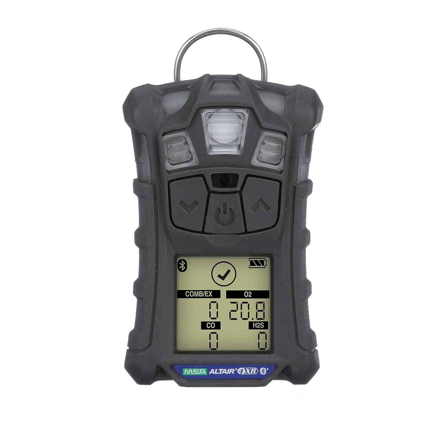
The 10 Most Common Industrial Gases (and Why We Detect Them)

Hydrogen Sulfide (H2S)

Hazard type

Toxic, flammable

Where you find it

Oil and gas production, refineries, wastewater plants, sewers, pulp and paper, biogas, manure storage

Hydrogen sulfide smells like rotten eggs at low levels, but that is exactly what makes it treacherous.

At around 100 ppm it can paralyze the sense of smell (olfactory fatigue), so the warning smell disappears while the danger increases. Higher concentrations can cause rapid collapse and death.

H2S is heavier than air, so it pools in low-lying areas, pits, sumps and confined spaces. Because of this, H2S is one of the most commonly monitored toxic gases in the world, and most four-gas portable detectors include it.

Carbon Monoxide (CO)

Hazard type

Toxic, flammable at high concentrations

Where you find it

Combustion processes, boilers, furnaces, engines, generators, steel and metal processing, parking structures

CO is colorless, odorless and tasteless. It binds to hemoglobin far more readily than oxygen does, starving the body of oxygen even when the air looks normal.

Early symptoms like headache and dizziness are easy to dismiss, which is why CO causes so many accidental poisonings.

Any place where fuel burns incompletely is a candidate for CO detection.

Methane (CH4) and Natural Gas

Hazard type

Combustible, asphyxiant at high concentrations

Where you find it

Natural gas pipelines, compressor stations, power plants, landfills, wastewater digesters, mining, commercial kitchens

Methane is the main component of natural gas. It is lighter than air and has a LEL of about 5% by volume.

A methane leak in an enclosed area can accumulate quietly until a spark finds it. Detection is usually done with catalytic bead or infrared sensors, with alarms set well below the LEL.

Oxygen (O2)

Hazard type

Deficiency (suffocation) or enrichment (fire)

Where you find it

Confined spaces, tanks, tunnels, inerted vessels, welding, medical and industrial oxygen systems

Oxygen is the “gas” that is detected for what it does not or should not do. A drop from 20.9% to below 19.5% signals an oxygen-deficient atmosphere.

Below about 16%, judgment and coordination decline, and at lower levels unconsciousness comes within minutes.

Oxygen enrichment is the opposite risk. In an oxygen-rich atmosphere, materials that normally burn slowly ignite violently. O2 sensing is a basic requirement for any confined space entry.

Carbon Dioxide (CO2)

Hazard type

Toxic at high levels, asphyxiant

Where you find it

Breweries and beverage plants, fermentation, food processing, dry ice storage, fire suppression systems, greenhouses, refrigeration

CO2 is not just a ventilation indicator. At elevated concentrations it affects breathing and can displace oxygen, and in confined or low areas it can accumulate because it is heavier than air.

The common occupational exposure limit is 5,000 ppm (8-hour TWA), and concentrations far higher than that can quickly become dangerous.

Infrared (NDIR) sensors are the standard choice for CO2 detection.

Ammonia (NH3)

Hazard type

Toxic, corrosive, flammable at high concentrations

Where you find it

Industrial refrigeration, food and cold storage, fertilizer production, chemical plants, water treatment

Ammonia is widely used as a refrigerant, so it appears in cold storage warehouses, meat and dairy plants, ice rinks and distribution centers.

It irritates eyes, skin and the respiratory tract. Because it is lighter than air, a release can rise and spread through the upper level of a room, which affects detector placement.

Chlorine (Cl2)

Hazard type

Toxic, strong oxidizer

Where you find it

Water and wastewater disinfection, swimming pool systems, chemical manufacturing, pulp and paper bleaching

Chlorine is heavy and highly irritating, attacking the eyes and lungs. Even low concentrations, around 1 ppm, are considered a ceiling-level concern in many regulations.

Chlorine detection is a core requirement at water treatment plants, where gas cylinders and feed systems are common.

Sulfur Dioxide (SO2)

Hazard type:

Toxic

Where you find it

Refineries, smelters, power generation (coal and oil combustion), sulfuric acid plants, food preservation, pulp and paper

SO2 is a sharp, irritating gas produced when sulfur-containing fuels or ores are burned. It attacks the respiratory system and is especially risky for workers with respiratory conditions. SO2 is a common emission and process-safety measurement in heavy industry.

Nitrogen Dioxide (NO2) and Nitrogen Oxides

Hazard type

Toxic, oxidizer

Where you find it

Combustion engines and exhaust, welding, explosives, nitric acid production, silage storage, tunnels and mines

NO2 is a reddish-brown gas with a harsh odor. Its danger is that lung damage can show up hours after exposure, so a worker may feel fine at the end of a shift and become seriously ill later. It is a concern in poorly ventilated spaces where engines or welding operate.

Hydrogen (H2) and Volatile Organic Compounds (VOCs)

Hazard type

Combustible (H2), toxic and flammable (VOCs)

Where you find it

Battery charging rooms, electrolysis, refining, fuel cells, solvent and paint operations, chemical plants

Hydrogen is the lightest gas, has a very wide flammable range (roughly 4% to 75% in air) and ignites with very little energy, so even a small leak deserves attention.

Battery rooms and green hydrogen projects are driving increased demand for hydrogen detection.

VOCs such as benzene, toluene and solvent vapors are detected with photoionization detectors (PIDs), because many are toxic at low ppm levels and some are carcinogenic.

Quick-Reference Comparison Table

GasPrimary hazardRelative to airTypical sensorCommon locations
Hydrogen sulfide (H2S)Toxic, flammableHeavierElectrochemicalOil and gas, wastewater
Carbon monoxide (CO)ToxicAbout the sameElectrochemicalCombustion, boiler rooms
Methane (CH4)CombustibleLighterCatalytic bead, infraredGas pipelines, landfills
Oxygen (O2)Deficiency / enrichmentn/aElectrochemicalConfined spaces
Carbon dioxide (CO2)Asphyxiant, toxicHeavierNDIR infraredBreweries, food plants
Ammonia (NH3)Toxic, corrosiveLighterElectrochemicalRefrigeration
Chlorine (Cl2)Toxic, oxidizerHeavierElectrochemicalWater treatment
Sulfur dioxide (SO2)ToxicHeavierElectrochemicalRefineries, smelters
Nitrogen dioxide (NO2)ToxicHeavierElectrochemicalEngines, welding, mining
Hydrogen (H2)CombustibleMuch lighterCatalytic, thermal conductivity, electrochemicalBattery rooms, electrolysis
VOCsToxic, flammableVariesPIDSolvents, chemical plants

Exposure limits and alarm setpoints vary by country, regulator and site policy. Always confirm values against your local regulations and the manufacturer’s documentation.

How Gas Properties Decide Where Detectors Go

Knowing which gas you have is only half the job. Where you put the detector matters just as much.

  • Lighter-than-air gases (methane, hydrogen, ammonia) rise, so detectors usually go high, near ceilings or roof peaks.
  • Heavier-than-air gases (H2S, chlorine, CO2, SO2) sink, so sensors belong low, near floors, sumps and pits.
  • Gases near air density (CO) mix more evenly, so detectors are often placed at breathing height.
  • Leak sources such as flanges, valves, compressors and cylinder connections deserve coverage nearby, because that is where a release begins.

Ventilation, airflow, temperature and the process itself also shift the right placement, which is why a proper gas mapping or risk assessment should come before any installation.

Matching the Sensor Technology to the Gas

No single sensor detects everything. The common technologies are

Electrochemical sensors

The workhorse for toxic gases and oxygen. They respond quickly and accurately at ppm levels.

Catalytic bead sensors

Long-established for combustible gases measured in %LEL. They need oxygen to work and can be affected by poisons such as silicones and sulfur compounds.

Infrared (NDIR) sensors

Used for hydrocarbons and CO2. They do not need oxygen, are not poisoned the way catalytic beads are, and offer fail-safe self-checking.

Photoionization detectors (PID)

Sensitive to VOCs at very low concentrations.

Paramagnetic and other specialty sensors

Used where specific measurement conditions require them.

Choosing the right technology for the gas, the environment and the failure mode is a large part of a good detection design.

Why Detection Matters Beyond Compliance

Regulations such as OSHA standards in the US, ATEX and IECEx for hazardous areas, and national occupational limits elsewhere require monitoring in many settings. But the reasons to detect go further:

Protecting lives

Early warning gives people time to evacuate or act.

Preventing explosions and fires

Detecting a leak at 10% LEL is far better than discovering it after ignition.

Protecting equipment and production

Leaks signal process problems before they become shutdowns.

Meeting insurance and legal duties

Documented detection and maintenance records support due diligence.

Supporting emergency response

Fixed systems can trigger ventilation, alarms and shutdowns automatically.

    A detector is only as good as its maintenance. Regular bump tests, calibration and sensor replacement are what keep a detection system trustworthy. A detector that has not been tested is an assumption, not a protection.

    Final Thoughts

    The most common industrial gases are common precisely because they are tied to everyday industrial processes: burning fuel, refining oil, treating water, refrigerating food and making chemicals.

    Each carries a specific hazard, and each calls for the right sensor, the right placement and a consistent maintenance routine.

    If you take away one principle, make it this: you cannot manage a hazard you cannot measure. Start with a clear picture of which gases your process can release, understand their properties, and build detection around them.

    Frequently Asked Questions

    What are the most common industrial gases?

    The gases most often monitored in industry are hydrogen sulfide (H2S), carbon monoxide (CO), methane and other combustible gases, oxygen (O2), carbon dioxide (CO2), ammonia (NH3), chlorine (Cl2), sulfur dioxide (SO2), nitrogen dioxide (NO2), hydrogen (H2) and volatile organic compounds (VOCs).

    Why do we need to detect industrial gases?

    Many hazardous gases are invisible, odorless or quickly numb the sense of smell. Detection provides early warning of toxic exposure, explosive atmospheres and oxygen deficiency so people can act before harm occurs.

    What does LEL mean in gas detection?

    LEL stands for Lower Explosive Limit, the lowest concentration of a flammable gas in air that can ignite.

    Detectors report combustible gas as a percentage of LEL, and alarms are typically set at a small fraction of it (often 10-20% LEL).

    What are the four gases in a standard four-gas detector?

    A standard four-gas portable detector commonly measures oxygen (O2), combustible gases (%LEL), hydrogen sulfide (H2S) and carbon monoxide (CO). These cover the most frequent hazards in confined space entry and general industrial work.

    Which gases are heavier than air?

    Hydrogen sulfide, carbon dioxide, chlorine, sulfur dioxide, nitrogen dioxide and propane are heavier than air and tend to collect in low areas. Methane, hydrogen and ammonia are lighter than air and tend to rise.

    How often should gas detectors be calibrated?

    Follow the manufacturer’s recommendations and your site’s safety program. Many organizations perform a bump test before each day’s use for portable detectors, with full calibration at regular intervals or whenever a bump test fails. Fixed detectors follow scheduled calibration based on the application and risk.

    Can one detector detect all gases?

    No. Different gases need different sensing technologies. Multi-gas detectors combine several sensors in one instrument, but each sensor targets specific gases, so the instrument must be matched to your hazards.

    Disclaimer

    This article is for general educational purposes. Exposure limits, alarm setpoints and legal requirements differ by jurisdiction and application.

    Always consult applicable regulations, your safety officer and the equipment manufacturer’s instructions before designing or operating a gas detection system.

    How Flame Detectors Work: UV, IR and UV/IR Explained

    A flame detector is an optical safety device that “sees” a fire by recognizing the radiation a flame gives off, usually within a second or a few seconds of ignition.

    Unlike smoke or heat detectors, it does not need to wait for smoke to rise or for air to heat up. That speed is why flame detectors guard refineries, compressor stations, offshore platforms, fuel loading racks, turbine enclosures and chemical plants.

    But not every flame detector works the same way. The three main technologies are ultraviolet (UV), infrared (IR) and combined UV/IR, with multi-spectrum IR (IR2, IR3) as the modern evolution of the IR family.

    Choosing the wrong one is one of the most common causes of missed fires and nuisance alarms.

    In this guide you will learn how a flame produces detectable radiation, how each detector type works, where each one fails, and how to choose the right one for your site.

    UV detectors sense the ultraviolet light of a flame, IR detectors sense the infrared radiation (especially the CO2 emission band near 4.3 µm) and its flicker, and UV/IR detectors require both signals before alarming. Multi-spectrum IR compares several infrared bands to reject false alarms.

    What Is a Flame Detector?

    A flame detector is a line-of-sight optical sensor that monitors a defined field of view for the radiation signature of a fire.

    It uses one or more optical sensors, filters and an electronic algorithm to decide whether what it sees is a real flame or just a harmless source such as sunlight, a welding arc or a hot pipe.

    Typical features of an industrial flame detector:

    • Field of view commonly around 90° to 120°
    • Detection range from roughly 15 m to more than 60 m, depending on technology, fuel and sensitivity setting
    • Outputs such as relay contacts, 4-20 mA, HART, Modbus or a network interface to the fire and gas system
    • Automatic optical integrity (OI) self-test that checks the window and optics
    • Hazardous-area enclosures (for example Ex d) for classified zones

    Because they depend on line of sight, flame detectors are placed using coverage mapping, not simply “one per room”.

    What Does a Flame Give Off? The Physics Behind Detection

    Every detection technology exploits a different part of the flame’s radiation.

    Ultraviolet radiation

    Flames emit UV, especially in the 180 to 260 nm range. This region is called “solar-blind” because the atmosphere absorbs most solar UV below roughly 280 nm, so sunlight does not normally reach a detector tuned to it.

    Infrared radiation

    Hydrocarbon fires (gasoline, diesel, natural gas, solvents, plastics, wood) produce carbon dioxide and water vapor, which radiate strongly in specific infrared bands.

    The best known is the CO2 emission peak near 4.3 to 4.4 µm. Hot CO2 in a flame radiates far more at this wavelength than ordinary hot surfaces do.

    Flicker

    A real flame pulsates at roughly 1 to 20 Hz. Detectors analyze this flickering pattern to separate flames from steady sources like a hot engine or a lamp.

    Fuel matters

    A hydrogen flame is almost invisible, produces no CO2, and emits mainly UV and a water-vapor infrared band.

    A metal or inorganic fire may have no strong CO2 band either. This is why the fuel in your process decides which detector is suitable.

    How UV Flame Detectors Work

    A UV flame detector senses ultraviolet radiation from the flame with a UV-sensitive sensor, traditionally a gas-filled tube working on the photoelectric effect.

    1. UV photons from the flame strike a metal cathode in the sensor.
    2. The cathode releases electrons, which are accelerated through the gas and trigger a pulse of current.
    3. The detector counts the pulses. A real fire produces a pulse rate above a set threshold, which then triggers the alarm after a short confirmation delay.

    Strengths of UV detectors

    • Very fast response, often under a second to a few seconds
    • Sensitive to a wide range of fuels, including hydrocarbons and hydrogen
    • Not affected by sunlight because they are solar-blind
    • Generally compact and economical

    Weaknesses of UV detectors

    • False alarms from arc welding, lightning, corona discharge, X-rays and some artificial lighting, all of which emit UV
    • Easily blinded by contamination. Oil mist, dirt, a thin film of water, or silicone can absorb UV and reduce sensitivity
    • Dense smoke and certain vapors (such as some solvent or hydrocarbon vapors) absorb UV and shorten detection range
    • Usually shorter range than modern multi-spectrum IR

    UV detectors still make sense in clean environments, enclosed areas where welding is controlled, and where hydrogen or other non-carbon fires are a concern.

    How IR Flame Detectors Work

    An infrared flame detector looks for the infrared signature of a flame, mainly the CO2 emission band around 4.3 to 4.4 µm, using a pyroelectric or thermopile sensor behind an optical filter.

    Single-band IR

    A single-band IR detector watches one narrow IR band and checks for flicker. It is simple and fairly low cost, but it can be fooled by anything hot and modulated, including:

    • Hot machinery or exhaust stacks
    • Reflected or direct sunlight in some conditions
    • Heaters and furnace walls
    • Rotating or moving objects that chop an IR source

    Because it only sees one band, it has little ability to tell a flame from other thermal sources, so it is mostly found in basic or legacy applications.

    Multi-spectrum IR (IR2 and IR3)

    Multiple-IR detectors (dual IR, triple IR and sometimes quad IR) watch several infrared bands at once, typically one at the CO2 peak and others on either side of it (reference bands). The algorithm compares the ratio and correlation between the bands.

    The logic is straightforward. A hydrocarbon flame produces a strong peak at 4.3 to 4.4 µm compared with the neighboring bands.

    A hot object or the sun produces a smooth, broadband spectrum with no such peak. By comparing bands, the detector can recognize the flame signature and reject the false source, in addition to checking the flicker.

    Strengths of multi-spectrum IR

    • Longest detection range, with high-end triple-IR models rated for well over 50 m on a standard test fire (always check the datasheet)
    • Strong immunity to sunlight, hot surfaces, welding and artificial light
    • Better performance than UV through light smoke, oil mist and dirty windows
    • Can see through thin contamination films that would blind a UV tube

    Weaknesses of IR

    • Weaker for fires that do not emit CO2 in quantity (hydrogen requires a detector specifically designed for it)
    • Atmospheric absorption by CO2 and water vapor, heavy rain, steam or fog reduces range
    • Higher cost than single-band UV or IR
    • Dense hydrocarbon gas or vapor clouds can absorb some IR bands

    How UV/IR Flame Detectors Work

    A UV/IR flame detector combines a UV sensor and an IR sensor (usually at the 4.4 µm CO2 band) in one housing.

    The key idea is voting: the detector alarms only when both sensors see a flame-like signature at the same time.

    Why this helps

    • A welding arc produces UV but little IR at the CO2 band, so the IR channel stays quiet and there is no alarm.
    • A hot pipe or the sun produces IR but not the right UV signature, so the UV channel stays quiet.
    • A real hydrocarbon fire produces both, so both channels trigger.

    Strengths of UV/IR detectors

    • Much better false alarm immunity than UV alone or single IR alone
    • Fast response, typically a few seconds
    • Proven technology with a long track record in hazardous areas

    Weaknesses of UV/IR detectors

    • Can miss hydrogen and other non-carbon fires, because those flames produce UV but little or no IR at the CO2 band, so the “both must agree” rule is never satisfied
    • Inherits the UV channel’s vulnerability to oil, dirt and water films on the window
    • Typically shorter range than triple-IR, often in the range of 15 to 30 m depending on the model
    • Smoke and vapors that absorb UV can desensitize the detector, even when the IR channel is fine

    Because of these limits, many new industrial projects now specify multi-spectrum IR as the default for hydrocarbon fires, while UV/IR remains common in existing plants and certain applications.

    UV vs IR vs UV/IR: Comparison Table

    FeatureUVSingle IRUV/IRMulti-spectrum IR (IR3)
    What it sensesUV, about 180–260 nmOne IR band (about 4.3 µm) plus flickerUV plus IR, both must agreeSeveral IR bands and flicker
    Response speedVery fastFastFastFast
    Typical rangeShort to mediumMediumShort to mediumLongest
    Sunlight immunityExcellent (solar-blind)Poor to moderateGoodExcellent
    Welding arc immunityPoorGoodGoodVery good
    Hot object immunityGoodPoorGoodVery good
    Hydrogen firesYesNoOften noOnly on special models
    Hydrocarbon firesYesYesYesYes
    Affected by oil, dirt, water filmStronglyModeratelyStrongly (UV channel)Less
    Relative costLowLow to mediumMediumHigher

    Treat the table as general guidance. Real performance varies by manufacturer, sensitivity setting and approval, so always confirm against the specific datasheet and approval documents.

    Which Fuels Can Each Detector See?

    Fire typeUVIR (single)UV/IRMulti-spectrum IR
    Hydrocarbons (gasoline, diesel, gas, solvents)YesYesYesYes
    HydrogenYesNoUsually noSpecial hydrogen-capable models only
    Metal firesSomeLimitedLimitedLimited
    Fires with heavy smoke (diesel, plastics)ReducedBetterReducedBetter

    If hydrogen, ammonia, silane, metal or other non-carbon fuels are present in your process, state them clearly to the manufacturer and ask for the exact fuel the detector was tested and approved against.

    What Affects Flame Detector Performance in the Field?

    A detector is only as good as what it can see. These are the factors that most often cause missed detection or nuisance alarms.

    Dirty or coated windows

    Oil film, dust, salt, paint overspray and ice reduce sensitivity, UV most of all. Regular cleaning and a working OI self-test are critical.

    Obstructions

    Pipes, structures, scaffolding or equipment blocking the line of sight create blind spots.

    Sensitivity settings

    Higher sensitivity increases range but also raises false alarm risk. Match the setting to the application.

    Environmental absorption

    Steam, heavy rain, fog, dense smoke and some vapors reduce range.

    Radiation sources

    Welding, grinding, flares, hot work, strong lighting and reflective surfaces can trigger or confuse detectors.

    Mounting position and angle

    Poor aiming or vibration reduces coverage.

    Fuel type and fire size

    Detection range is rated for a specific fire size, usually a standard test fire such as a 0.1 m² (about 1 ft²) n-heptane pan. Smaller or different fires are seen at shorter distances.

    How to Choose the Right Flame Detector

    Use this practical checklist:

    Identify the fuels

    Hydrocarbon only, or hydrogen and non-carbon fuels too?

    List false-alarm sources

    Welding, flares, sunlight, hot equipment, lighting.

    Consider the environment

    Indoor or outdoor, oil mist, steam, dust, salt, extreme temperatures.

    Define the coverage need

    Required distance, field of view and acceptable blind spots, ideally verified by fire and gas mapping.

    Check approvals

    Hazardous-area ratings (ATEX, IECEx or similar), performance approvals such as FM 3260 or EN 54-10 where applicable, and SIL suitability if the detector is part of a safety instrumented function.

    Plan integration

    Confirm outputs (relay, 4-20 mA, HART, Modbus) match your fire and gas controller.

    Plan maintenance

    Cleaning access, OI test, periodic functional testing with a manufacturer-approved test lamp.

      Rule of thumb: for most hydrocarbon facilities, multi-spectrum IR is the most robust general choice. UV or UV/IR may still fit controlled or legacy applications, and hydrogen service needs a detector explicitly approved for hydrogen.

      Common Mistakes to Avoid

      • Using UV/IR in a hydrogen area without confirming hydrogen capability
      • Installing UV detectors near welding or hot-work zones without bypass procedures
      • Ignoring window cleaning until the OI fault appears
      • Choosing a detector on range alone, without checking fuel and approvals
      • Skipping functional tests because the detector “has a self-test”

      Frequently Asked Questions

      How does a flame detector work?

      A flame detector uses optical sensors to look for the radiation a flame emits, such as ultraviolet light, infrared radiation and the characteristic flicker of a fire.

      When the signal matches a flame signature, it triggers an alarm or output to the fire and gas system.

      What is the difference between UV and IR flame detectors?

      UV detectors sense the ultraviolet light from a flame and respond very fast, but welding arcs and lightning can set them off.

      IR detectors sense infrared radiation, mainly the CO2 band, and handle dirt and smoke better, but hot objects and sunlight can affect simple single-band models.

      What is a UV/IR flame detector?

      It is a flame detector that has both a UV sensor and an IR sensor and needs both to agree before alarming.

      This reduces false alarms from welding or hot surfaces, though it can miss fires that do not produce IR, such as hydrogen.

      Which is better, UV/IR or triple IR?

      For most hydrocarbon applications, triple IR (IR3) offers longer range and stronger false alarm rejection, which is why it is widely specified on new projects.

      UV/IR can still be a good fit in some existing or specific applications. The best choice depends on the fuel, environment and approvals.

      Can flame detectors see hydrogen fires?

      UV detectors can, because hydrogen flames emit UV. Standard IR and most UV/IR detectors may not, since hydrogen produces no CO2. Use a detector specifically approved for hydrogen.

      How far can a flame detector see?

      Range depends on the technology, fuel, fire size and sensitivity setting. Some UV and UV/IR models are rated at roughly 15 to 30 m, while advanced multi-spectrum IR detectors can exceed 50 m for a standard test fire. Always use the manufacturer’s range curves.

      Can flame detectors give false alarms?

      Yes. UV detectors can respond to welding arcs and lightning, and simple IR detectors to hot surfaces and modulated sources.

      Multi-spectrum IR and UV/IR detectors greatly reduce this, but good placement, correct sensitivity and procedures for hot work are still essential.

      Final Thoughts

      Flame detectors work by recognizing the optical fingerprint of a fire. UV detectors are fast and sensitive but easy to fool and easy to blind.

      Single IR adds flicker and the CO2 band but struggles with hot sources. UV/IR combines two views to cut false alarms, with a blind spot for hydrogen.

      Multi-spectrum IR compares several bands for the longest range and best rejection of false sources in hydrocarbon fires.

      The right choice always starts with your fuel, your environment and your false alarm sources, and it must be backed by correct placement and regular maintenance.

      A well-chosen detector that is cleaned and tested will protect people and assets far better than an expensive one left to fend for itself.

      Related reading on SafeguardSense: flame detector fault diagnostics, false alarms in gas detection, and how gas detectors integrate with fire and gas systems.

      Best Practices for Gas Detection in Chemical Plants

      A gas release in a chemical plant rarely announces itself. A flange gasket weeps, a pump seal degrades, a relief valve lifts, and within seconds an invisible cloud can drift toward people, ignition sources or a control room air intake.

      Gas detection in chemical plants is the layer of protection that turns that invisible hazard into an alarm, a shutdown or an evacuation in time to matter.

      But owning detectors is not the same as having a working gas detection system. In my experience as an automation engineer working with gas detection and safety systems, the plants with the best safety records are not the ones with the most expensive hardware.

      They are the ones that apply a handful of disciplined practices consistently: assessing hazards properly, choosing the right technology, placing detectors where gas will actually go, setting sensible alarms, and keeping every sensor verified and healthy.

      This guide walks through those best practices step by step.

      Start with a gas hazard assessment

      Every good gas detection design begins with a clear answer to one question: what can leak, where, and what happens next?

      Use your existing process safety work (HAZOP, LOPA, process hazard analysis) as the foundation, then build a gas-specific view on top of it:

      Identify every hazardous gas and vapor

      Flammable (hydrocarbons, hydrogen, solvent vapors), toxic (hydrogen sulfide, chlorine, ammonia, carbon monoxide, hydrogen chloride, phosgene) and oxygen deficiency or enrichment.

      Record the properties that drive detection

      Vapor density relative to air, lower explosive limit (LEL), exposure limits (TWA, STEL, IDLH), pressure, temperature and boiling point.

      Map release scenarios

      Flange and valve leaks, pump and compressor seals, loading and unloading, sample points, vents, relief discharges, tank breathing and process upsets.

      Identify what needs protection

      Operators, nearby communities, control rooms, motor control centers, ignition sources and critical equipment.

      Define the safety objective for each scenario

      Is the detector there to trigger an alarm, a shutdown, ventilation, deluge or evacuation? The objective determines the required speed, reliability and voting logic.

      Document this assessment. It becomes the basis for your detector layout, your alarm philosophy and your auditing evidence later.

      Choose the right sensing technology

      No single sensor works for every gas or every environment. Choosing technology is a trade-off between selectivity, response time, maintenance burden and failure behavior.

      TechnologyTypical useStrengthsLimitations
      Catalytic beadFlammable gases and vapors (%LEL)Proven, low cost, broad hydrocarbon responseCan be poisoned (silicones, H2S, chlorinated compounds), needs oxygen, can fail silently if not tested
      Infrared (NDIR) pointHydrocarbons, CO2Not poisoned, works without oxygen, self-diagnosticsNot suitable for hydrogen, can be affected by condensation or fouled optics
      Open-path / line-of-sight IRPerimeters, large areas, long leak pathsCovers wide areas, fast detection of gas crossing the beamAffected by fog, heavy rain and misalignment, measures path-integrated concentration
      ElectrochemicalToxic gases (H2S, CO, Cl2, NH3) and oxygenSpecific, sensitive at ppm levels, low powerLimited life, affected by temperature, humidity and cross-sensitivity, needs regular calibration
      PID (photoionization)VOCs at low ppmVery sensitive to many organicsNot specific, lamp and window fouling, humidity effects
      Metal oxide semiconductorHydrogen and some toxic gasesRugged and long-lived in some applicationsCross-sensitivity, baseline drift
      Ultrasonic leak detectionHigh-pressure gas leaksDetects the sound of the leak, not the gas, works in windDoes not measure concentration, background noise must be assessed
      UV/IR flame detectorsFire from flammable liquids and gasesFast flame detectionDetects flame, not gas, needs a clear line of sight

      A few practical rules:

      • Use two technologies where one failure mode is unacceptable. For example, combining infrared point detectors with open-path detectors, or catalytic with infrared, reduces common-cause failure.
      • Prefer sensors with diagnostics. Detectors that self-check optics, report sensor health and signal faults over HART or digital protocols are far easier to keep reliable.
      • Look at what can poison or foul the sensor in your specific process before you decide. A catalytic sensor in a plant with silicone or sulfur compounds needs a deliberate plan.
      • Verify the certification. Detectors in hazardous areas must carry the appropriate approval for the area classification (for example ATEX/IECEx or the North American equivalent), and detector performance should be tested to the relevant standard such as IEC 60079-29-1 for flammable gas detectors.

      Place detectors where gas will actually go

      Poor placement is one of the most common reasons a technically good system fails in practice. The detector can be perfectly calibrated and still never see the leak.

      Consider gas density

      • Lighter than air (hydrogen, methane, ammonia): mount detectors high, near ceilings, roof peaks and ventilation exhausts.
      • Heavier than air (propane, butane, chlorine, hydrogen sulfide, most solvent vapors): mount detectors low, near grade, pits, trenches, sumps and low-lying areas where gas collects.
      • Near neutral density (carbon monoxide): mount in the breathing zone and near likely sources.

      Remember that temperature, pressure and mixing can change this behavior. A cold, pressurized release of a light gas may initially travel downward. Always confirm placement with release scenarios rather than density alone.

      Focus on leak sources and receptors

      • Place detectors near likely leak sources: compressors, pumps, flanged connections, valve manifolds, loading arms and sample stations.
      • Place detectors at receptors: air intakes for control rooms, switchrooms and analyzer shelters, and near ignition sources such as furnaces, generators and non-rated electrical equipment.
      • For toxic gases, place detectors between the source and the people you are protecting, not only at the source.

      Respect airflow and the environment

      • Study prevailing wind direction, ventilation patterns, obstructions, enclosures and dead zones.
      • Use scenario-based and geographic coverage approaches together. Scenario-based coverage targets credible leaks, while geographic coverage looks for the area that a gas cloud of a defined size could reach. Guidance such as ISA-TR84.00.07 describes how to evaluate the effectiveness of gas detection coverage.
      • Install detectors where technicians can reach them for testing and calibration. A detector that is difficult to access will eventually be tested less often.

      Use 3D gas dispersion modeling or CFD for complex, congested or high-consequence areas. It is much cheaper than discovering a blind spot after an incident.

      Read: Gas Detector Mounting Height Guide: Where to Install Gas Detectors and Why?

      Set alarm levels and response actions with intent

      Alarm setpoints should be derived from hazard data and the response you want, not copied from another plant.

      HazardCommon practice (examples only)Notes
      Flammable gasLow alarm around 10 to 25% LEL, high alarm around 40 to 60% LELHigher stages typically trigger shutdown or ventilation actions
      Oxygen deficiencyAlarm at 19.5% O2Common regulatory reference for oxygen-deficient atmospheres
      Oxygen enrichmentAlarm at 23.5% O2Enriched atmospheres increase fire risk
      Toxic gasesBased on TWA, STEL and IDLH valuesFor example, H2S, Cl2 and NH3 each need setpoints tied to their own exposure limits and local regulations

      Treat these as starting points. Your site’s risk assessment, local regulations and manufacturer data decide the final values.

      Good alarm design also means

      Define a response for every alarm level

      Who does what at low alarm? What automatically happens at high alarm?

      Use voting logic for shutdown functions

      Two-out-of-three (2oo3) or two-out-of-two (2oo2) voting reduces spurious trips, while one-out-of-two (1oo2) favors safety. Choose according to the consequence of both a missed event and a false trip.

      Apply alarm management principles

      Rationalize alarms against standards such as ISA-18.2 so operators are not buried in nuisance alarms.

      Make fault signals distinct from gas alarms

      A detector in fault must never look like a detector reading zero.

      Design for functional safety (SIL) where required

      When gas detection initiates a safety instrumented function, such as isolating a feed or shutting down a compressor, it becomes part of a safety instrumented system and must be designed accordingly.

      • Follow IEC 61511 for process industry safety instrumented systems and IEC 61508 for the devices themselves.
      • Select detectors with appropriate SIL capability and proven failure data (for example, SIL 2 certified detectors where the risk assessment demands it).
      • Calculate the required probability of failure on demand and set proof test intervals that actually meet it.
      • Remember that SIL is a system property. The detector, the transmitter, the wiring, the logic solver and the final element all contribute.

      In regions covered by process safety regulations such as OSHA PSM (29 CFR 1910.119) or the EPA RMP rule in the United States, documented gas detection, maintenance and testing are also part of demonstrating compliance.

      Bump test, calibrate and document

      The most common reason gas detection fails is not bad design. It is lack of verification.

      Bump (functional) testing exposes the detector to a known gas concentration to confirm it responds and alarms. Calibration adjusts the detector’s reading to match a known standard.

      • Portable detectors: industry guidance, such as the ISEA statement on verification of calibration, recommends a bump test before each day’s use.
      • Fixed detectors: functional checks and calibration intervals are commonly in the range of every three to six months, but should be set from manufacturer instructions, sensor history, the environment and the safety function.
      • Use certified calibration gas within its expiry date, with the correct regulator and flow rate for the sensor, and the correct test gas or a verified surrogate for the target gas.
      • Test the full loop. Include alarm outputs, shutdown logic, beacons, horns and DCS indication, not just the sensor reading.
      • Record everything. Date, technician, gas used, as-found and as-left readings, and any sensor replacement. Trend as-found results. A sensor that repeatedly needs large span adjustments is telling you it is near end of life.

      If zero or span readings become hard to correct, see my guide on troubleshooting zeroing and span issues in gas sensors.

      And if you are seeing declining response, review the signs a gas sensor needs replacement before the next scheduled calibration.

      Manage sensor life, poisoning and environmental effects

      Sensors age and the plant environment accelerates it.

      • Catalytic sensors can lose sensitivity through poisoning or inhibition by silicones, sulfur compounds, lead and halogenated compounds. Regular testing with the target gas is essential.
      • Electrochemical sensors have a finite life and can dry out or saturate in extreme humidity and temperature.
      • Infrared sensors can be affected by dirty optics, condensation and misalignment.
      • Weather protection: use sunshields, splash guards, dust screens and appropriate collecting cones, but verify they do not slow the response to gas.
      • Cross-sensitivity: know which interferents your sensors respond to, such as hydrogen on a CO sensor, to avoid false alarms and false confidence.

      Track sensor installation dates and plan replacements proactively rather than waiting for failure.

      Integrate detection into your control and safety architecture

      Detectors work best as part of a coordinated system.

      • Connect to the fire and gas system and the DCS or PLC so alarms, faults and diagnostics are visible to operators and trigger the correct automated actions.
      • Use diagnostic-rich signals. A 4-20 mA signal with NAMUR NE43-style fault levels (for example, below about 3.8 mA) lets the system distinguish a fault from a true zero. HART or Modbus communication adds device health, calibration status and remote configuration.
      • Supervise the wiring and power. Open circuits, short circuits and loss of power must be detected and alarmed.
      • Coordinate with other layers. Link gas alarms to ventilation, isolation valves, emergency shutdown, deluge or water curtains and public address systems as your safety philosophy requires.
      • Consider data analytics and fleet management. Centralized software for portable and fixed devices makes bump test compliance, calibration schedules and event history much easier to manage and audit.

      Don’t forget portable and personal gas monitoring

      Fixed detection protects areas. Portable and personal detectors protect people, especially during maintenance, turnarounds and confined space entry.

      • Issue multi-gas personal monitors (typically O2, LEL, CO and H2S, plus additional sensors as needed) to personnel entering process areas.
      • For confined space entry, test the atmosphere in the correct order: oxygen first, then flammable gases, then toxic gases, and test at multiple levels because gases can stratify.
      • Make sure the detector, sampling pump and tubing are suitable for the task, and keep continuous monitoring in place during the work.
      • Link portable detector use to your permit-to-work system.

      Train people and test the response

      A perfect detector layout still fails if people do not know what the alarms mean.

      • Train operators, maintenance technicians and emergency teams on each alarm level and the required action.
      • Run drills that include gas alarms, shelter-in-place, evacuation and rescue scenarios.
      • Include gas detection in your management of change process so new equipment, modifications or process changes trigger a review of coverage.
      • Audit the system regularly and review incidents and near misses for lessons.

      Common mistakes to avoid

      1. Placing detectors on a uniform grid without considering density, airflow or leak sources.
      2. Skipping bump tests and relying only on scheduled calibration.
      3. Using the wrong calibration gas or an expired cylinder.
      4. Ignoring sensor poisoning, cross-sensitivity and environmental effects.
      5. Setting alarms so low or so many that operators ignore them.
      6. Treating fault signals as non-events.
      7. Failing to update coverage after process or layout changes.
      8. Leaving test and maintenance records incomplete, which makes audits and root cause analysis harder.

      Quick checklist for chemical plant gas detection

      AreaQuestion to ask
      Hazard assessmentHave all gases, release scenarios and receptors been documented?
      TechnologyIs each sensor type suitable for the gas, environment and failure mode?
      PlacementAre detectors positioned by density, leak sources, airflow and ignition sources?
      AlarmsAre setpoints justified and every alarm tied to a defined action?
      Functional safetyDo safety functions meet the required SIL and proof test intervals?
      VerificationAre bump tests, calibration and full-loop tests scheduled and documented?
      MaintenanceAre sensor age, poisoning risk and environmental protection managed?
      IntegrationAre faults, alarms and diagnostics visible in the control system?
      PeopleIs training current and are drills realistic?
      Change controlIs coverage reviewed whenever the plant changes?

      Frequently asked questions

      What is the best type of gas detector for a chemical plant?

      There is no single best type. Chemical plants typically use a combination: infrared or catalytic detectors for flammable gases, electrochemical sensors for toxic gases and oxygen, open-path detectors for large areas, and portable monitors for personnel. The right mix depends on the gases present, the environment and the required safety function.

      How often should gas detectors be calibrated in a chemical plant?

      Follow the manufacturer’s instructions and your risk assessment. Portable detectors should be bump tested before each day’s use.

      Fixed detectors are commonly calibrated every three to six months, with more frequent checks in harsh environments or where sensors are prone to drift.

      What is the difference between a bump test and calibration?

      A bump test confirms the detector responds to gas and triggers its alarms. Calibration adjusts the detector so that its reading matches a known gas concentration. Bump testing verifies function, while calibration restores accuracy.

      How many gas detectors do I need?

      The number depends on plant layout, leak sources, airflow and the coverage target defined in your assessment.

      Instead of using a rule of thumb, use scenario-based and geographic coverage analysis, often supported by dispersion modeling.

      Are fixed gas detectors enough, or do I also need portable detectors?

      You need both. Fixed detectors monitor process areas continuously, while portable and personal detectors protect individuals during maintenance, inspection and confined space entry where fixed coverage cannot reach.

      Which standards apply to gas detection in chemical plants?

      Common references include IEC 60079-29-1 (performance of flammable gas detectors), IEC 60079-29-2 (selection, installation, use and maintenance), IEC 61511 and IEC 61508 (functional safety), ISA-TR84.00.07 (effectiveness of fire and gas systems) and local regulations such as OSHA PSM or equivalent. Always confirm the standards required in your jurisdiction.

      Final thoughts

      Effective gas detection in chemical plants is not a product you buy once. It is a lifecycle: assess the hazard, select and place the right detectors, set meaningful alarms, integrate with your safety systems, then verify and maintain relentlessly.

      Plants that treat gas detection as a living system, supported by good data and well-trained people, are the ones that catch small leaks before they become incidents.

      If you are reviewing an existing system, start with the checklist above and be honest about where the gaps are. A single missed bump test program or an outdated detector layout can matter more than any upgrade in hardware.

      Disclaimer

      This article is for general educational purposes. Always follow applicable regulations, manufacturer instructions and your site’s engineered safety requirements, and consult qualified safety professionals for specific designs.

      Why Flame Detectors Are Critical in Industrial Safety Systems

      A hydrocarbon fire can grow from a small ignition to a plant-wide emergency in a matter of seconds.

      In that window, the difference between a contained incident and a catastrophic one is usually how fast the fire is detected and how fast the plant responds.

      That is the job of flame detectors in industrial safety systems. Unlike smoke or heat detectors, which wait for combustion products or temperature to reach them, flame detectors “see” the radiation a fire gives off and react almost immediately.

      They are the eyes of a fire and gas (F&G) system in places where seconds matter: refineries, offshore platforms, fuel loading terminals, turbine halls, chemical plants, and more.

      In this guide you’ll learn how flame detectors work, why they outperform other fire detection methods in industrial settings, where they are required, and what to look for when designing or maintaining a flame detection system.

      What Is a Flame Detector?

      A flame detector is an optical fire detection device that senses the radiant energy emitted by a flame (ultraviolet, visible, and infrared light) and triggers an alarm or a safety action when it recognizes the signature of a fire.

      Because they detect radiation rather than waiting for smoke or heat to reach them, flame detectors work at a distance, in open areas, and in places where air movement would carry smoke and heat away from a conventional detector.

      Why Flame Detectors Are Critical in Industrial Safety Systems

      They detect fire faster than smoke or heat detectors

      Radiation travels at the speed of light. A flame detector can respond to a fire in a fraction of a second to a few seconds, depending on the technology and the distance.

      A smoke or heat detector has to wait for combustion products or temperature to build up and reach the sensor, which can take far longer, especially outdoors or in high-ceiling areas.

      In process industries, that time gap decides whether you shut down a feed, isolate a process section, and start suppression before escalation, or after.

      They work where other detectors can’t

      Industrial areas are hard environments for conventional detection.

      • Outdoor process units where wind disperses smoke and heat
      • High-bay buildings and turbine enclosures where heat and smoke stratify far from the detector
      • Large open areas such as tank farms, loading racks, and offshore decks
      • Areas with strong ventilation where combustion products are diluted or pulled away

      Flame detectors have a defined field of view and range, so a single detector can cover a large open area without relying on airflow to bring the fire to it.

      They can detect fires that produce little or no smoke

      Many industrial fuels burn cleanly. Fires involving hydrogen, methanol, and some other fuels can produce little visible smoke and may be hard to see to the human eye, especially in daylight.

      Optical flame detection, chosen with the correct spectral sensitivity for the fuel, is one of the few reliable methods for catching them early.

      They are a key layer in the fire and gas system

      Flame detection is not a standalone safeguard. It works together with gas detection, manual call points, and the control logic that decides what happens next.

      When a gas detector warns of a developing leak and a flame detector confirms ignition, the F&G system can execute a coordinated response: alarms, process shutdown, depressurization, ventilation changes, deluge, or fire-water activation.

      If you want to understand how those layers connect, read our guide on how gas detectors integrate with fire and gas systems.

      They protect people, assets, and uptime

      The case for flame detection comes down to three outcomes

      • People: earlier alarms mean earlier evacuation and a lower chance of injury.
      • Assets: faster response limits fire damage to equipment and structures.
      • Business continuity: a contained incident can be the difference between a short outage and a prolonged shutdown, insurance claims, and regulatory investigation.

      How Flame Detectors Work

      Flame detectors analyze the light emitted by a fire. Different detector types look at different parts of the spectrum and apply different logic to decide whether what they see is really a fire.

      Ultraviolet (UV) flame detectors

      UV detectors respond to the ultraviolet radiation from a flame. They are very fast, often reacting in well under a second, and are sensitive to a wide range of fuels.

      The trade-off is that they can be triggered by other UV sources such as arc welding, lightning, and some lighting, and their windows can be degraded by oil mist, smoke, or contamination.

      Single-frequency infrared (IR) flame detectors

      Single IR detectors look for the characteristic flicker of a flame in a narrow infrared band, most commonly around the 4.3 micron CO₂ emission band.

      They are suited to carbon-containing fuels but can be vulnerable to false alarms from hot surfaces, modulated sources, and sunlight if not well designed.

      UV/IR flame detectors

      Combining UV and IR sensing requires both channels to agree before alarming. This improves immunity to many false-alarm sources (for example, a welding arc triggers UV but not the IR channel) while keeping good sensitivity. UV/IR is common in indoor industrial areas with controlled conditions.

      Multispectral IR (IR3 and IR4) flame detectors

      Triple IR (IR3) and multi-IR detectors compare radiation across several narrow infrared bands and look at the ratios and flicker patterns between them.

      This gives the best false-alarm immunity and the longest detection range, often several tens of metres for a standard hydrocarbon test fire, and is the typical choice for outdoor hydrocarbon facilities such as oil and gas, petrochemical, and refining.

      Visual (video-based) flame detection

      Video flame detection uses cameras and analytics to identify flames and, in some products, smoke.

      It is useful for very large areas or where visual verification adds value, and it is often used as a complement to optical flame detectors rather than a replacement.

      Flame Detector Types Compared

      Detector typeTypical strengthsTypical limitationsCommon applications
      UVVery fast response, wide fuel rangeSensitive to arc welding, lightning, window contaminationIndoor areas, enclosures with controlled conditions
      Single IRGood for hydrocarbon fires, lower costMore prone to false alarms from hot objects and sunlightLimited, well-understood environments
      UV/IRBetter false-alarm immunity than UV or IR aloneShorter range than multispectral IRTurbine halls, compressor stations, indoor process areas
      IR3 / Multi-IRLongest range, strongest false-alarm rejection, good outdoorsHigher cost, requires correct fuel and application selectionRefineries, offshore, loading terminals, tank farms
      Video-basedVisual verification, large coverage areasNeeds lighting and analytics tuning, complements rather than replacesLarge open areas, remote monitoring

      Ranges and response times vary by manufacturer, model, fuel, and sensitivity setting. Always confirm values against the manufacturer’s data sheet and approval documents.

      Where Flame Detectors Are Used

      Flame detectors are typically installed wherever a flammable liquid or gas fire is credible and fast detection is essential:

      • Oil and gas production, refining, and petrochemical plants
      • Offshore platforms and FPSOs
      • Fuel loading racks, terminals, and tank farms
      • Gas turbine and compressor enclosures
      • Hydrogen production, storage, and handling areas
      • Aircraft hangars and fuel handling areas
      • Chemical and pharmaceutical process areas using flammable solvents
      • Power generation facilities

      Standards, Approvals, and Safety Integrity

      Flame detectors in hazardous areas are expected to meet recognized standards and approvals. The ones you will see most often include:

      • Fire detection performance approvals such as FM 3260 (radiant energy-sensing fire detectors) and EN 54-10 for flame detectors.
      • Hazardous area certification such as ATEX, IECEx, or North American Class/Division and Zone approvals, depending on the region and the classification of the area.
      • Functional safety per IEC 61508 and IEC 61511, where the flame detector acts as the input of a safety instrumented function and a specific SIL target applies.
      • Design guidance such as NFPA 72 and company or industry practices for fire and gas mapping.

      If your flame detector initiates a shutdown or suppression function, its safety integrity matters as much as its detection performance. See our article on SIL 2 and SIL 3 requirements in gas detection for how these targets are applied in practice.

      What Can Go Wrong: Limitations Engineers Must Plan For

      Flame detectors are powerful, but they are not magic. Good design and maintenance address their known weaknesses.

      False alarms

      Common sources include welding arcs, hot work, reflections of sunlight off water or metal, flares, hot exhausts, and modulated lights.

      Choosing the right technology (typically multispectral IR in outdoor hydrocarbon service) and the right sensitivity is the first line of defense. We cover causes and prevention in detail in False Alarms in Gas Detection: Causes and Prevention.

      Blocked or dirty optics

      A dirty window is a blind detector. Oil film, dust, salt, ice, paint, and condensation all reduce sensitivity.

      Many modern detectors include automatic optical integrity checks (often called oi or “eye test”) that report when the window has lost sensitivity, but cleaning schedules are still essential.

      Obstructed line of sight

      Flame detectors need a clear view of the hazard. Pipe racks, tanks, structures, and temporary scaffolding can create blind spots. Detector placement should be validated through fire mapping, not guesswork.

      Wrong detector for the fuel

      Detectors are tuned to the radiation of particular fuels. A detector selected for hydrocarbon pool fires may not be appropriate for hydrogen, metals, or some other fuels. Always match the detector’s spectral response and approvals to the fuels actually present.

      Environmental effects

      Heavy rain, fog, steam, dense smoke, and extreme temperatures can reduce range. This is why engineers apply derating and design margins rather than relying on the maximum quoted range. For related effects on gas detection, see How Environmental Conditions Affect Gas Detectors.

      Faults and degradation over time

      Like any instrument, flame detectors can develop faults related to power, wiring, optics, or internal diagnostics. If you are chasing a recurring fault, our flame detector fault diagnostic guide walks through the checks step by step.

      Best Practices for Flame Detection Design and Maintenance

      Start with a hazard assessment

      Identify credible fire scenarios, fuels, and consequences before choosing technology.

      Perform fire and gas mapping

      Use fire mapping to determine detector locations, aiming, coverage, and voting logic, including blind spots from equipment and structures.

      Select the right technology for the fuel and environment

      Match detector type, approvals, and sensitivity to the actual hazards and conditions.

      Use voting logic where appropriate

      Voting (for example 2oo3) reduces spurious trips while keeping the ability to detect real fires.

      Plan access for maintenance

      Detectors that are hard to reach tend to be cleaned and tested less often.

      Test regularly

      Use manufacturer-approved test lamps or procedures to verify response, not just wiring continuity.

      Keep optics clean and document it

      Set a cleaning interval based on the environment, and review trends in diagnostic data.

      Manage bypasses and hot work

      Control inhibits and overrides through a formal permit and management of change process, and make sure they are restored afterward.