How to Select the Right Fixed Gas Detector in 11 Steps

I have been working in the gas detection industry for the last 8 years and one of the most frequently question i get is how to select the right fixed gas detector.

How to Select the Right Fixed Gas Detector 

Whether it is for your own application or you are helping the customer to select the right solution for them, this is the right sequence of questions and steps I go.

Step 1: Define the Hazard

This is the first step, you want to know what you are dealing with, you need to identify exactly what you are trying to detect, some of the most common hazards are the following.

  • Flammable gases (methane, propane, hydrogen, solvents)
  • Toxic gases (H₂S, CO, NH₃, Cl₂, silane, arsine)
  • Oxygen deficiency or enrichment
  • Volatile Organic Compounds (VOCs)

These are the questions you need to ask 

        What gas could be released?

  • What concentration is dangerous?
  • Is the primary concern toxicity, explosion risk, or oxygen displacement?

A detector must be selected for the specific target gas. No single technology can detect every gas effectively.

Step 2: Understand the Application

Knowing the specific gas they you want to detect is not enough, you need to determine where the detector will be installed. 

Here are some of the examples.

ApplicationTypical Hazard
RefineryHydrocarbon leaks
Chemical plantToxic gas releases
Semiconductor facilitySpecialty toxic gases
Wastewater treatmentH₂S, CH₄
Boiler roomCO, natural gas
Refrigeration plantNH₃
Battery roomH₂ accumulation

The environment often dictates the detector technology and housing requirements. Honeywell industrial references highlight different detector solutions for oil & gas, chemical processing, wastewater, cold storage, and semiconductor applications.

Step 3: Select the Proper Sensor Technology

Selecting the right sensor technology is crucial for the gas detection system to work as it was designed, depending of the type of gas and environment you can select the right sensor for the application, here are some of the technologies recommended depending on what is the target gas.

Electrochemical Sensors

Best for:

  • CO
  • H₂S
  • NH₃
  • O₂
  • Cl₂

Advantages:

  • High sensitivity
  • Excellent ppm-level measurement

Limitations:

  • Limited sensor lifespan
  • Potential cross-sensitivity

Catalytic Bead Sensors

Best for:

  • Combustible gases
  • General LEL detection

Advantages:

  • Broad combustible gas response
  • Cost effective

Limitations:

  • Can be poisoned by contaminants
  • Requires oxygen to function

Infrared (IR) Sensors

Best for:

  • Hydrocarbon gases
  • CO₂

Advantages:

  • Resistant to poisoning
  • Low maintenance
  • Fast response

Honeywell’s Searchpoint Optima Plus IR detector is designed for harsh industrial environments where catalytic poisons may be present. 

PID Sensors

Best for:

  • VOCs
  • Solvents

Advantages:

  • Highly sensitive
  • Fast response

Limitations:

  • Requires regular calibration

Ultrasonic Gas Leak Detectors

Best for:

  • Pressurized gas releases
  • Outdoor windy environments

Advantages:

  • Detects leaks before a gas cloud reaches a sensor

Step 4: Determine Detection Range

I have seen customers who select a 0 to 250 ppm co detector in an application that the co leaks can reach to 500 ppm and the detector is in constant overrange and it is alarming all the time.

You need to figure out the range of the leaks expected in your application and select the sensor range acordingly.

Select an appropriate measurement range.

Examples:

Gas TypeTypical Range
H₂S0–100 ppm
CO0–500 ppm
Oxygen0–25% vol
Methane0–100% LEL

The range must match both:

  • Expected operating concentrations
  • Safety limits

Step 5: Evaluate Environmental Conditions

You need to select your detector depending on the environment, for example if you want to detect Methane in normal environment you need a maybe the catalytic bead sensor is the best option but if you want to detect the same gas (methane) in the environment where the O2 levels are less than 10%, the infrared sensor is the best option.

Here are conditions you need to consider.

Temperature

  • Extreme heat or cold

Humidity

  • Condensation risk
  • Corrosive environments

Dust and Water

  • IP66/IP67 requirements

Vibration

  • Compressors
  • Rotating equipment

Corrosive Atmospheres

  • Offshore platforms
  • Chemical plants

Detector materials should be selected accordingly, often using stainless steel in harsh environments. 

Step 6: Choose Point Detection or Open-Path Detection

In fixed gas detection you can select to detect the gas at a specific point or on a certain path.

Point Detectors

Used when:

  • Leak source is known
  • Monitoring pumps, valves, flanges, compressors

Pros:

  • Highly localized measurement
  • Lower cost

Open-Path Detectors

Used when:

  • Large areas need coverage
  • Perimeters or fence lines require monitoring

Pros:

  • Covers long distances
  • Detects moving gas clouds

Many facilities use a combination of both technologies. 

Step 7: Determine Detector Placement

The location of the sensor is critical, you need to study the guy you are detection and check it is relative density ( you can find this on the msds).

For Light Gases

Install high.

Examples

  • Hydrogen
  • Methane

For Heavy Gases

Install low.

Examples:

  • Propane
  • Butane
  • H₂S

Also you need to consider the following.

  • Leak sources
  • Airflow patterns
  • Ventilation systems
  • Obstructions

A poorly placed detector can miss a leak even if the detector itself is correct.

Step 8: Verify Required Certifications

Certifications are important, they are both required by local authorities and insurance companies.

Depending on the location of your project, check with local authorities and figure out which certifications are needed.

Typical certifications include

  • ATEX
  • IECEx
  • UL
  • CSA
  • FM

Industrial installations often require detectors certified for hazardous locations. Honeywell fixed gas detection products include multiple global certifications for hazardous-area applications. 

Step 9: Consider System Integration

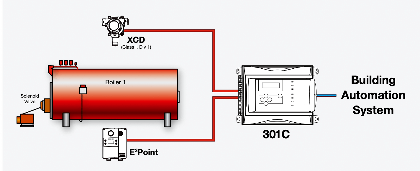
Fixed detector usually are connected to a larger control or building management system, you need to select the detector that can easily integrate with the current or future system.

Determine how the detector will communicate with the control system.

Common outputs

  • 4-20 mA
  • HART
  • Modbus
  • Relay outputs

Also verify compatibility with:

  • DCS
  • PLC
  • Gas controllers
  • Safety systems

Many modern transmitters support multiple communication methods and hot-swappable sensors to simplify maintenance.

Step 10: Evaluate Maintenance Requirements

Before you commit to buy the detector, you need to contact the manufacturer or the distributor and check what is the maintenance requirements like calibrations, you need to understand the frequency and the procedure, you need to figure out if your technicians will need new training or they can do it with minimum training.

These are some questions you can ask yourself.

  • How often must calibration be performed?
  • What is the expected sensor life?
  • Are replacement sensors available?
  • Can calibration be performed remotely?

Consider total lifecycle cost, not just purchase price.

Step 11: Perform a Risk-Based Coverage Assessment

This step with help you to figure out how many detectors you need, and to make sure that the area is protected properly.

Create a detector mapping study

  1. Identify credible leak sources.
  2. Determine gas release scenarios.
  3. Model dispersion patterns.
  4. Confirm detector coverage.
  5. Validate alarm actions.

A detector that is technically correct but poorly located provides little protection.

Quick Selection Matrix

If You Need to DetectRecommended Technology
H₂SElectrochemical
COElectrochemical
OxygenElectrochemical
MethaneIR or Catalytic
HydrocarbonsIR or Catalytic
CO₂IR
VOCsPID
High-pressure gas leaks outdoorsUltrasonic

Final Rule of Thumb

When selecting a fixed gas detector, always answer these five questions first:

  1. What gas am I detecting?
  2. What concentration must be detected?
  3. Where will the detector be installed?
  4. What environmental conditions exist?
  5. What action should occur when gas is detected?

If these five questions are answered correctly, the proper detector technology, location, and system architecture usually become clear.

Gamma Radiation Detector: How They Work, Detection Technologies, and How to Choose One

If you work anywhere near radioactive sources, radiography operations, nuclear facilities, or even certain oilfield logging tools, a gamma radiation detector isn’t optional equipment. It’s the instrument standing between a normal shift and an unrecognized overexposure.

Gamma radiation is invisible and silent and passes through most everyday materials, which is precisely why relying on your senses to know it’s there is not a strategy.

This guide walks through what gamma radiation actually is, why detection matters in industrial and safety settings, how gamma sensors work at a physical level, the detection technologies you’ll encounter on the market, and a practical framework for choosing the right detector for your application.

What Is Gamma Radiation?

Gamma radiation is a form of electromagnetic radiation, similar to visible light or X-rays, but with much higher energy and frequency.

It’s emitted from the nucleus of certain unstable (radioactive) atoms as they decay toward a more stable state. Unlike alpha or beta particles, which are actual pieces of matter ejected from an atom, gamma rays carry no mass and no electric charge. They’re pure energy traveling as photons.

That lack of mass and charge is precisely what makes gamma radiation so penetrating. Alpha particles can be stopped by a sheet of paper or the outer layer of skin.

Beta particles need a few millimeters of plastic or aluminum. Gamma rays, on the other hand, require dense shielding, such as thick lead, concrete, or steel, to attenuate them meaningfully.

They can pass through the human body, through walls, and through most industrial equipment casings.

Common sources of gamma radiation include the following:

  • Naturally occurring radioactive materials (NORM), found in some oil and gas production scales and certain mineral deposits.
  • Industrial radiography sources (such as cobalt-60 and iridium-192) used for non-destructive testing of welds and pipelines.
  • Medical isotopes used in diagnostic imaging and cancer treatment.
  • Nuclear power generation and spent fuel handling.
  • Certain well-logging tools are used in oil and gas exploration.

Because gamma rays can’t be seen, smelled, or felt until biological damage has already occurred, detection instruments are the only reliable way to know gamma radiation is present, at what intensity, and whether it exceeds a safe threshold.

Why Do You Need to Detect Gamma Radiation?

The case for gamma detection rests on three key points: it is invisible, it is cumulative, and the consequences of missing it can be severe.

Human senses can’t detect it

There is no smell, sound, or visual cue associated with gamma exposure. Someone standing next to an unshielded source has no biological warning system telling them to move away.

Exposure is dose-dependent and cumulative

Radiation damage to tissue is a function of both intensity and time. A detector doesn’t just tell you radiation is present.

It quantifies dose rate (µSv/h or mR/h) and, on personal dosimeters, accumulated dose over a shift, month, or career. That data is what keeps workers within regulatory exposure limits.

Regulatory and liability exposure

Facilities working with radioactive sources, radiography operations, and NORM-handling sites are typically governed by national nuclear regulatory bodies (in the U.S., the NRC; in Mexico, the CNSNS; and equivalent agencies elsewhere) as well as international guidance from the IAEA. Documented, calibrated gamma detection is often a licensing and audit requirement, not a nice-to-have.

Beyond compliance, gamma detectors serve several practical field functions: locating lost or damaged radiography sources, verifying that shielding is adequate before workers re-enter an area, screening scrap metal loads for contamination, and confirming that transport packages of radioactive material meet regulatory dose-rate limits at the surface and at one meter.

How a Gamma Radiation Sensor Works

Every gamma detection technology relies on the same underlying principle: gamma photons interact with a detector material and transfer some of their energy to it, producing a measurable signal, either an electrical pulse, a flash of light, or a change in electrical conductivity.

The instrument’s electronics count these interaction events and convert the count rate into a dose rate reading.

The three physical interaction mechanisms that make this possible are

Photoelectric effect

A gamma photon is fully absorbed by an atom in the detector, ejecting an electron. This dominates at lower gamma energies and in high-density materials.

Compton scattering

A gamma photon transfers only part of its energy to an electron and continues at a lower energy, at an altered angle.

This is the dominant interaction across most of the energy range that detectors encounter in the field.

Pair production

At very high photon energies (above 1.022 MeV), a gamma photon can convert into an electron-positron pair.

This interaction is less common in typical industrial detection scenarios but relevant in higher-energy nuclear physics applications.

Whichever interaction occurs, the result is a burst of ionization or excitation inside the detector medium.

The detector’s job is to capture that burst, convert it into an electronic pulse, and pass it to a counting circuit.

The instrument then applies a calibration factor (tied to a specific isotope, usually Cesium-137, unless energy-compensated) to translate counts per second into a dose-rate unit like µSv/h.

Response time, energy dependence, and sensitivity all vary by the underlying detection technology, which is where the choice of sensor type becomes important.

Gamma Radiation Detection Technologies

Gamma detectors on the market today fall into three broad technology families, each with distinct trade-offs in sensitivity, cost, ruggedness, and application fit.

Geiger-Müller (GM) Tubes

The GM tube is the most widely deployed gamma detection technology because it’s simple, rugged, and inexpensive relative to its alternatives.

It consists of a gas-filled tube (typically a halogen-quenched noble gas) with a high-voltage anode wire running through the center.

When a gamma photon ionizes the gas, the resulting avalanche of electrons produces a detectable current pulse.

Strengths

Low cost, mechanically robust, simple electronics, wide availability, good for general area monitoring and survey work

Limitations

Lower sensitivity than scintillation detectors, meaning slower response at low dose rates; limited energy discrimination (can’t distinguish isotopes); “dead time” after each pulse can cause undercounting at very high dose rates

GM-based survey meters and personal dosimeters are the workhorse instruments for radiography crews, emergency responders, and general area surveys where identifying the specific isotope isn’t the goal, just confirming presence and intensity.

Scintillation Detectors

Scintillation detectors use a crystal (commonly sodium iodide doped with thallium, NaI(Tl)) or a plastic scintillator that emits a flash of visible light when struck by gamma radiation.

That light is captured by a photomultiplier tube (PMT) or solid-state photodiode and converted into an electronic pulse proportional to the energy deposited.

Strengths

Significantly higher sensitivity than GM tubes, making them well-suited to detecting low-level or shielded sources; the pulse height is proportional to photon energy, enabling spectroscopic identification of specific isotopes in higher-end units

Limitations

More expensive, more fragile (crystal can be sensitive to shock and temperature swings), higher power consumption, PMTs add bulk

Scintillation-based instruments are the standard for radioisotope identification devices (RIIDs), portal monitors at scrap yards and border crossings, and search operations where a weak or shielded source needs to be located from a distance.

Semiconductor (Solid-State) Detectors

Semiconductor detectors, most notably high-purity germanium (HPGe) and cadmium zinc telluride (CZT), generate an electrical signal directly when gamma photons create electron-hole pairs in the crystal lattice, without an intermediate light-conversion step.

Strengths

Excellent energy resolution (HPGe in particular is the gold standard for laboratory-grade isotope identification), compact form factor for CZT-based handheld identifiers

Limitations

HPGe requires cryogenic cooling for lab-grade performance, making it impractical for rugged field use; CZT units are more affordable and portable but still carry a significant cost premium over GM and standard scintillation instruments

Semiconductor detectors show up most often in laboratory analysis, homeland security screening, and premium handheld isotope identifiers, where precise energy resolution justifies the added cost.

TechnologySensitivityIsotope IDRuggednessRelative CostTypical Use
Geiger-MüllerModerateNoHighLowArea survey, personal dosimetry, radiography checks
Scintillation (NaI)HighYes (with MCA)ModerateModerate–HighSearch & locate, portal monitoring, isotope ID
Semiconductor (CZT/HPGe)HighExcellentLow–ModerateHighLab analysis, high-precision field ID

How to Select the Right Gamma Radiation Detector

Choosing a gamma detector comes down to matching the instrument’s capability to the actual hazard and workflow, not simply buying the most sensitive unit available. Work through these criteria:

Define the application first

A radiography crew doing daily source-retrieval checks has different needs than a scrapyard screening incoming metal loads for orphan sources, and both differ from a personal dosimetry program tracking cumulative worker dose.

Area survey vs. personal exposure monitoring vs. isotope identification are three distinct instrument categories.

Match sensitivity to the dose-rate range you expect

GM-based instruments are perfectly adequate for confirming the presence of radiation at moderate-to-high dose rates but will respond slowly at very low levels.

If you’re searching for weak or shielded sources, a scintillation-based instrument is worth the added cost.

Decide whether isotope identification matters

If your job is simply to confirm “radiation present, evacuate,” a basic survey meter or dosimeter will suffice.

If you need to know whether you’re looking at a medical isotope, an industrial radiography source, or a security threat, you need a spectroscopic instrument (scintillation with a multichannel analyzer or a semiconductor-based RIID).

Check the energy response range

Gamma-emitting isotopes span a wide energy range from around 60 keV (Americium-241) to over 1,300 keV (Cobalt-60). Confirm the detector’s calibrated energy response covers the isotopes relevant to your site.

Consider environmental ruggedness

Field instruments used in oilfield, construction, or emergency response settings need an IP-rated enclosure, intrinsic safety certification if used in classified areas, and a wide operating temperature range. Lab-grade instruments with cryogenic cooling requirements simply won’t survive field conditions.

Verify calibration and traceability

Any gamma detector used for regulatory compliance or worker safety should have a documented calibration traceable to a national standards body with a defined recalibration interval, typically annual, though check your local regulatory requirements.

Battery life and alarm functionality

For personal dosimeters and survey meters used on long shifts, confirm battery runtime against your actual shift length, and check whether audible/vibration alarms are configurable to your site’s dose-rate action levels.

Data logging and connectivity

For programs tracking cumulative worker dose or feeding into a broader safety monitoring system, look for units offering data logging, Bluetooth or wireless connectivity, and export compatibility with your existing EHS or radiation safety software.

Gamma Detectors vs. Other Radiation Detection Instruments

It’s worth being clear that a gamma radiation detector is not a universal radiation instrument. Alpha and beta contamination require dedicated pancake-probe or thin-window detectors, since gamma-optimized sensors are largely blind to those particle types.

Neutron detection (relevant near reactors or certain industrial neutron sources) requires yet another detector technology entirely, typically based on helium-3 or boron-lined proportional counters.

If your site has mixed radiation hazards, you’ll likely need a combination instrument or separate dedicated detectors rather than expecting one gamma-only unit to cover everything.

FAQ

What’s the difference between a Geiger counter and a gamma radiation detector?

A Geiger counter is one specific type of gamma (and beta) radiation detector, built around a Geiger-Müller tube.

“Gamma radiation detector” is the broader category that also includes scintillation and semiconductor-based instruments, which offer higher sensitivity and, in some cases, isotope identification that a basic Geiger counter can’t provide.

How far can a gamma radiation detector sense a source?

Detection range depends on the source’s activity, the detector’s sensitivity, and shielding between the source and the instrument.

High-sensitivity scintillation detectors can locate stronger sources from several meters away, while weaker or well-shielded sources may only be detectable at close range or not at all without a more sensitive instrument.

Do gamma radiation detectors need regular calibration?

Yes. Gamma detectors drift over time as components age, and most regulatory frameworks require documented calibration against a certified reference source at regular intervals, usually annually, with functional response checks done more often.

Can a gamma radiation detector also detect X-rays?

Many gamma detectors will also respond to X-rays since both are high-energy electromagnetic radiation and the underlying detection physics (photoelectric effect and Compton scattering) is the same.

However, instrument sensitivity and calibration at typical X-ray energies should be confirmed with the manufacturer if X-ray detection is a specific requirement.

What dose rate should trigger an alarm on a gamma detector?

Alarm setpoints depend on your regulatory framework and site-specific radiation safety program, not a universal number.

Most personal dosimeters and area monitors are configurable, and setpoints should be established by a qualified radiation safety officer based on applicable occupational dose limits.

Is a gamma radiation detector the same as a dosimeter?

Not always. A survey meter reads instantaneous dose rate and is typically used for area or source surveys. A dosimeter is worn by an individual and tracks accumulated dose over time.

Some modern instruments combine both functions, but they serve different primary purposes in a radiation safety program.

Point Gas Detector vs Multipoint Sampling System: Which One Fits Your Facility?

If you’ve ever sat in a design review arguing over whether a process area needs a bank of fixed-point detectors or a single multipoint sampling panel pulling from a dozen locations, you already know this isn’t a trivial choice.

It affects your capital budget, your maintenance workload, and most importantly, how fast your team finds out about a leak.

I’ve specified both architectures across industrial gas detection projects, and the honest answer is that neither one is universally “better.” They solve different problems.

This article breaks down how each system actually works, where each one wins, and how to decide which belongs in your facility or whether you need both.

What Is a Point Gas Detector?

A point gas detector is a standalone sensor installed directly at a specific monitoring location, such as a compressor skid, a tank farm valve manifold, or a confined-space entry point.

The sensor sits in the actual atmosphere it’s monitoring, using catalytic bead, electrochemical, infrared, or photoionization sensing elements depending on the target gas.

Because the sensor is physically present at the hazard, it reads gas concentration in near-real time. There’s no transport lag, no tubing to clog, no sample pump to fail. Each point detector reports independently to the control system or safety controller, typically over 4-20 mA, HART, or a digital fieldbus protocol.

Where point detectors are the obvious choice.

  • A small number of well-defined, high-consequence release points.
  • Locations where response time is critical (H2S near a wellhead, for example).
  • Areas where running sample tubing is impractical or where tubing itself would need to cross classified hazardous zones.
  • Facilities that already have SIL-rated fixed detection integrated into their safety instrumented system.

The tradeoff is scalability. Once you’re monitoring 15, 20, or 30 points across a sprawling process unit, the cabling, junction boxes, and per-point maintenance (calibration, bump testing, sensor replacement) start adding up fast both in capital cost and in technician hours.

What Is a Multipoint Sampling System?

A multipoint sampling system, sometimes called a sequential sampling or extractive multiplexed system, uses a central analyzer (often a single, higher-quality NDIR or electrochemical bench) connected to multiple remote sample points through a network of tubing and a solenoid-driven sampling manifold.

The system pulls air sequentially from each point back to the central unit for analysis, cycling through locations at set intervals.

Instead of buying and maintaining 20 individual sensors, you maintain one analyzer and a set of sample lines, filters, and a pump.

That’s the core value proposition: fewer sensing elements to calibrate, one point of analytical truth, and centralized diagnostics.

Where multipoint sampling makes sense

  • Large numbers of monitoring points spread across a wide area (tank farms, warehouse HVAC returns, large confined spaces with multiple sample locations).
  • Environments where sensor exposure to dust, moisture, or corrosive atmosphere would shorten the life of individual field-mounted sensors.
  • Applications where a slightly slower response time is acceptable in exchange for lower long-term maintenance costs.
  • Facilities standardizing on one analytical technology for consistency across many locations.

The tradeoff is response time and mechanical complexity. Every additional sample point in the sequence adds to the cycle time before that specific location gets re-checked.

If you have 12 points on a 60-second sample time each, a given location might only be re-sampled every 10-12 minutes.

Tubing runs are also a maintenance liability of their own: they can develop leaks, kinks, condensation blockages, or biological fouling over time, and a single pump or manifold failure takes the whole system down rather than just one point.

Point Detector vs Multipoint Sampling: Side-by-Side Comparison

FactorPoint (Fixed) DetectorMultipoint Sampling System
Response timeSeconds, sensor is in the atmosphereMinutes. Depends on sample cycle time and tubing length
Number of sensing elementsOne sensor per monitored pointTypically one central analyzer for many points
Capital cost (small point count)Lower for under ~6-8 pointsHigher, central analyzer plus tubing infrastructure
Capital cost (large point count)Scales linearly, gets expensive fastScales more efficiently past 10-15 points
MaintenancePer-sensor calibration and bump testingSingle analyzer calibration, plus tubing/filter/pump upkeep
Failure modeIndependent. One sensor failure doesn’t affect othersShared risk. Pump, manifold, or analyzer failure affects all points
Best for hazardous area routingSensor mounted directly, minimal cable-only routingRequires sample tubing routed through the hazardous area
Typical use caseHigh-consequence, fast-response locationsWide-area monitoring with many lower-urgency points
Integration with SISCommon, well-established for SIL-rated loopsLess common for SIL applications due to sample lag

Response Time: The Deciding Factor for Many Applications

This is usually where the decision actually gets made. If you’re protecting a confined space entry, a compressor seal, or any location where a release could reach IDLH concentration within a minute or two, the sample transport lag of a multipoint system is a genuine safety concern, not just an inconvenience.

Sample line length, tubing diameter, and pump flow rate all add delay on top of the sequential cycle time between points.

For slower-developing hazards, a warehouse with a refrigerant leak that would take time to accumulate or a tank farm perimeter where you’re looking for trend data rather than instant alarm, the extra minutes of lag from a multipoint system are usually acceptable, especially given the cost and maintenance savings.

If you’re unsure how detection technology affects response and reliability, it’s worth understanding how NDIR sensors handle response time and battery life and how condensation can distort infrared gas readings before committing to an architecture. The sensing technology inside either system has its own set of failure modes worth knowing about.

Maintenance and Total Cost of Ownership

Point detectors win on simplicity per unit but lose on aggregate labor. Once you’re past a dozen points, each sensor needs its own calibration gas, bump test schedule, and eventual sensor cell replacement (catalytic sensors are particularly prone to poisoning from silicones and sulfur compounds; see our breakdown of why catalytic sensors get poisoned if that’s part of your process environment).

Multipoint systems concentrate that maintenance burden into fewer analytical units but shift it toward mechanical upkeep: sample line integrity checks, filter replacement, pump diaphragm wear, and periodic verification that tubing hasn’t developed a leak or blockage that would silently invalidate readings from an entire point.

A tubing leak in a multipoint system is a particularly sneaky failure. It can pull ambient air instead of sample air and read artificially clean without tripping an obvious fault.

Neither system is “low maintenance.” They just distribute the maintenance burden differently. Per-sensor labor versus centralized-analyzer-plus-tubing-network labor.

Can You Combine Both Architectures?

In practice, most larger industrial sites do exactly this. Point detectors get deployed at the small number of high-consequence, fast-response locations near compressors, at confined space entries, and at flammable gas release points feeding directly into the safety instrumented system.

A multipoint sampling system then handles the wider net of lower-urgency locations where centralized trending and lower per-point cost matter more than seconds of response time.

This hybrid approach is common in tank farms, wastewater treatment facilities, and large manufacturing plants where the risk profile genuinely varies by location.

Treating every point the same, whether with all fixed detectors or an all-sampling system, usually means overspending in one area and undershooting response time in another.

Frequently Asked Questions

Is a point gas detector always faster than a multipoint sampling system?

Generally yes. A point detector’s sensor sits directly in the atmosphere it monitors, so there’s no transport delay.

A multipoint system has to physically pull a sample through tubing back to a central analyzer, and that location has to wait its turn in the sampling sequence. Both factors add lag that a point detector doesn’t have.

How many monitoring points does it take before a multipoint system becomes more cost-effective?

There’s no universal number, but many facilities find the crossover somewhere around 10-15 points, depending on tubing run lengths and site layout.

Below that, the capital cost of a central analyzer and sampling infrastructure often isn’t justified compared to just installing individual point detectors.

Can a multipoint sampling system be used for SIL-rated safety instrumented functions?

It’s uncommon, mainly because of the sample transport lag and shared failure mode (a single pump or manifold fault affects every point).

Most SIL-rated gas detection loops use fixed-point detectors specifically because they respond independently and quickly enough to meet the required safety integrity level.

What causes a multipoint sampling system to give a false clean reading?

The most common cause is a tubing leak upstream of the sample point, which lets the system pull in ambient air instead of the actual sample.

Blocked or crushed tubing, a failing sample pump, or a clogged particulate filter can also starve the analyzer of representative sample air without triggering an obvious system fault.

Do point detectors and multipoint systems use the same sensor technology?

They can both use architectures that are compatible with catalytic bead, electrochemical, infrared (NDIR), and photoionization detection principles.

The difference is architectural, not about the underlying sensing technology. It’s about where the sensing happens (at the point or centrally after sample transport) rather than what kind of sensor does the sensing.

Bottom Line

Choose a point detector when speed and independence matter most, and your point count is manageable.

Choose a multipoint sampling system when you’re covering a large number of locations and centralized analytics and lower per-point maintenance outweigh the cost of a few minutes of sample lag.

And on larger or higher-risk sites, don’t be afraid to run both, matching the architecture to the actual consequence severity at each location, rather than forcing one system to do a job it wasn’t designed for.

This article draws on hands-on field experience specifying, installing, and maintaining fixed and portable industrial gas detection systems across process safety applications.

Why Silane Detection Is Different from Ordinary Toxic-Gas Monitoring

If you’ve spent any time around fixed or portable gas detection, it’s tempting to treat every gas as a variation on the same theme: pick a sensor, set an alarm point, calibrate on a schedule, move on. Silane (SiH4) breaks that pattern.

It’s one of the few gases in industrial use where the toxic-gas playbook is not just incomplete. It can actively get someone hurt if it’s the only playbook you’re using.

I’ve worked with gas detection systems across semiconductor, solar-panel manufacturing, and specialty chemical environments, and silane consistently trips up teams that are otherwise very competent at industrial safety.

This article breaks down exactly why silane behaves differently, where standard toxic-gas monitoring falls short, and what a correct detection strategy actually looks like.

Silane Isn’t Just Toxic: It’s Pyrophoric

The core issue is that silane carries two independent hazard profiles at once, and most detection programs are only built for one of them.

Toxicity

Silane has an OSHA PEL of 5 ppm as an 8-hour TWA. At elevated concentrations, it’s an irritant and asphyxiant, and it can cause serious respiratory harm.

On paper, this looks like a fairly ordinary toxic-gas problem, similar in scale to something like arsine or phosphine.

Pyrophoricity

This is where silane leaves the ordinary toxic-gas category entirely. Silane spontaneously ignites on contact with air at room temperature, with no ignition source required.

No spark, no hot surface, no static discharge needed. It just burns. This is fundamentally different from flammable gases like methane or propane, which need an ignition source and enough oxygen within their flammable range before they’ll combust.

Because of that pyrophoric behavior, a silane leak doesn’t sit around waiting to accumulate to its Lower Flammable Limit (LFL) of roughly 1.37% before becoming dangerous.

It’s dangerous the moment it contacts air, at concentrations far below LFL. That single fact reshapes almost every design decision in a silane detection system.

Where Toxic-Gas Monitoring Logic Falls Apart

A conventional toxic-gas monitoring program is built around a specific hazard model: gas accumulates, concentration rises past a PEL-based threshold, and the alarm gives people time to evacuate or don PPE before harm occurs. That model assumes you have a meaningful buffer between “detectable” and “dangerous.”

Silane collapses that buffer in three specific ways.

Alarm Setpoints Can’t Be Based on Toxicity Alone

If you set silane alarms purely against the 5 ppm PEL, you’re treating it like a chronic-exposure hazard.

But the acute hazard of ignition happens at concentrations that have nothing to do with the PEL.

A well-designed silane system typically uses a low-level alarm well below PEL for toxic exposure control, plus a separate, more aggressive response tied to leak detection and shutdown logic, because by the time you’re thinking about LFL percentages, silane has often already ignited.

Response Time Requirements Are Tighter

With most toxic gases, a sensor response time of 30-60 seconds to reach a stable reading is workable, because the hazard develops over minutes.

With silane, the entire hazard sequence, leak, ignition, and fire, can happen in seconds. Detection systems built for silane service are typically specified for faster response, tighter sensor placement near known leak points (valve manifolds, gas cabinets, purge panels), and direct interlocks to automatic shutoff valves rather than relying on manual response to an alarm.

Sensor Technology Choice Changes

This is the part that catches people off guard. The two most common toxic-gas sensor technologies, electrochemical and standard catalytic bead, both have real limitations with silane.

  • Electrochemical sensors can work for silane, but they’re often not fast enough or sensitive enough at the low-ppm range needed to catch a leak before it becomes an ignition event, and cross-sensitivity to other process gases in semiconductor fabs (like phosphine or diborane) can produce false readings.
  • Standard catalytic bead sensors, which are the default for flammable-gas LFL monitoring, are poorly suited to silane specifically because silane’s spontaneous combustion at the sensor surface can damage the bead over time, and catalytic sensors aren’t calibrated to catch the sub-LFL concentrations where silane is already hazardous.

Most well-designed silane systems instead lean on specialty electrochemical sensors tuned specifically for silane or infrared/point-IR technology in some installations, paired with conservative placement and redundancy, not because the underlying detection principle changes, but because the acceptable margin for error shrinks dramatically.

Comparison: Silane vs. a Typical Toxic Gas (H₂S)

FactorHydrogen Sulfide (H₂S)Silane (SiH₄)
Primary hazardToxicityToxicity + pyrophoric ignition
Reacts with air at room tempNoYes, spontaneously
Alarm basisPEL / STEL thresholdsLow-ppm toxicity alarm + leak/shutdown logic
Acceptable response timeTens of secondsSeconds
Consequence of undetected leakChronic/acute exposureFire, potential explosion
Typical sensor technologyElectrochemicalSilane-specific electrochemical or IR tighter placement
Redundancy expectationsStandardHigher, often paired with automatic shutdown

What a Sound Silane Detection Strategy Actually Looks Like

In practice, the sites that handle silane well share a few common traits.

They treat it as two hazards, not one

Toxic exposure control and pyrophoric leak/fire prevention get separate alarm logic, not a single blended setpoint.

Sensors sit close to the source

Gas cabinets, valve manifold boxes, and purge points get dedicated point detection rather than relying on area monitors alone.

Detection ties directly into automatic shutoff

Given how fast silane can ignite, waiting on a human response to a control room alarm isn’t fast enough for the highest-risk points.

Excess flow valves and automatic shutoffs are common companions to the detection system itself.

Sensor selection accounts for cross-sensitivity

In fabs running multiple specialty gases, cross-sensitivity between silane sensors and other process gases gets evaluated explicitly, not assumed away.

Calibration schedules reflect the consequence of failure, not just manufacturer defaults

Because a false negative on silane has a much worse outcome than a false negative on most toxic gases, bump testing and calibration intervals tend to run tighter than the standard 6-month/annual cycle common elsewhere.

FAQ

Is silane more dangerous than other toxic gases?

It carries a real toxic exposure hazard, but what sets it apart is the added pyrophoric risk. It ignites spontaneously in air, which most toxic gases don’t do. That combination is what demands a different detection approach.

Can I use a standard flammable-gas (LFL) sensor for silane?

Standard catalytic LFL sensors aren’t well suited to silane. They’re built to catch percentage-of-LFL concentrations, while silane becomes hazardous through ignition well below that threshold, and the combustion event itself can damage a catalytic bead over time.

What alarm setpoint should silane systems use?

This depends on the facility’s process safety documentation and applicable codes, but the key principle is that toxicity-based PEL alarms and pyrophoric leak-detection alarms are typically treated as separate layers, not one combined number.

Does silane detection require automatic shutdown, or is an audible alarm enough?

Given how quickly silane can ignite after a leak, many facilities pair detection with automatic excess-flow valves or shutoff systems at the highest-risk points, rather than relying solely on personnel response to an alarm.

Where should silane sensors be placed?

Close to known leak sources such as gas cabinets, valve manifold boxes, and purge panels rather than only at the room or area level, since the hazard develops too fast for area-level detection alone to catch it in time.

This article reflects general industry practice for silane detection and is not a substitute for a site-specific process hazard analysis or the requirements of your local fire and safety code. Always coordinate detection system design with a qualified process safety engineer.

Remote Sampling vs Direct Gas Detection: Which Method Fits Your Application?

Choosing between remote sampling and direct (diffusion-based) gas detection is one of the most consequential decisions in a gas detection system design and one that’s frequently made backwards, with the sensor technology picked before the sampling method is even considered.

Get it wrong, and you end up with a detector that’s technically accurate but physically incapable of catching a leak in time, or a system so maintenance-heavy that operators start bypassing it.

This guide breaks down how each method actually works in the field, where each one earns its keep, and how to make the call for your specific application, drawing on hands-on experience specifying and commissioning both types of systems in industrial environments.

What “Remote Sampling” and “Direct Detection” Actually Mean

Before comparing performance, it’s worth being precise about what these terms describe, because they’re often used loosely.

Direct (diffusion) gas detection places the sensor itself at the point where gas is expected to accumulate.

Ambient air diffuses naturally across the sensor element. No pump, no tubing. The sensor reads the air right where it sits.

Remote sampling (aspirated/extractive) detection separates the sensing element from the sample point.

A pump draws air through tubing from one or more remote locations back to a centrally located sensor or analyzer. The gas is measured “remotely” relative to where it’s actually present.

Both approaches can use the same underlying sensor technologies: catalytic bead, infrared (NDIR), electrochemical, or photoionization.

The difference is entirely in how the sample reaches the sensor, not in the sensing chemistry itself.

How Direct Detection Works in Practice

A diffusion-type detector relies on passive gas movement. Because there’s no pump pulling air through the unit, placement is everything: the sensor has to physically sit where the target gas is likely to be, accounting for vapor density, ventilation patterns, and likely leak points.

Typical applications

  • Fixed point detectors mounted near compressors, valves, or flanges.
  • Confined space monitors positioned at breathing zone height.
  • Area monitors in process areas with known leak sources.
  • Portable single- and multi-gas personal monitors.

Because the sensor is exposed directly to ambient conditions, direct detection tends to respond faster to a local leak.

There’s no transit time through tubing. It’s also mechanically simpler: fewer failure points, no pump to maintain, no tubing to crack or clog.

The tradeoff is coverage. A diffusion sensor only “sees” gas that reaches it by natural diffusion or air currents.

In areas with poor air movement, or where the leak source could be anywhere across a large or inaccessible space, a fixed grid of diffusion detectors gets expensive fast, and you can still miss pockets between units.

How Remote Sampling Works in Practice

An aspirated system uses a pump (integral or centralized) to actively draw air samples through tubing from one or more remote points to the sensor housing. This decouples sensor placement from sample point location entirely.

Typical applications

  • Hazardous or hard-to-access locations (tank interiors, ductwork, elevated equipment, pits).
  • Locations too hot, wet, or corrosive for a sensor to survive directly.
  • Multi-point monitoring from a single centralized analyzer.
  • Locations requiring the electronics to sit in a non-hazardous or easily serviceable area.

Because the sensor and its electronics can be mounted somewhere accessible and environmentally protected, remote sampling is often the only practical option in harsh or physically inaccessible locations.

It also enables true multipoint sequential sampling, one analyzer cycling through several sample points, which can reduce the total sensor count and calibration burden versus installing a diffusion detector at every location.

The tradeoff is response time and system complexity. Every meter of sample tubing adds transport lag before the gas reaches the sensor.

Long tubing runs, small-bore tubing, or low flow rates can push response times well past what a diffusion sensor would show for the same leak.

The pump, tubing, filters, and any moisture traps are additional components that need inspection, and a blocked or cracked line can silently defeat the entire system, a failure mode that direct detection doesn’t have.

Side-by-Side Comparison

FactorDirect (Diffusion) DetectionRemote Sampling (Aspirated) Detection
Response timeFast, gas reaches sensor by ambient diffusionSlower; depends on tube length, bore, and flow rate
Sensor placementMust be at or very near the leak sourceSensor can be located away from the sample point
Best for hazardous/hot/wet areasThe limited sensor is directly exposedWell suited; sensors and electronics stay protected
Multi-point monitoringRequires one detector per pointOne analyzer can sequence multiple sample points
Mechanical complexityLow, no pump or tubingHigher, pump, tubing, filters, possible moisture traps
Failure modesSensor drift, poisoning, physical damageTubing blockage, leaks, pump failure, in addition to sensor issues
Maintenance burdenSensor calibration/replacement onlySensor calibration plus tubing integrity checks and pump service
Typical calibration approachCalibration gas applied directly at the sensor.Calibration gas often applied at the sample point to validate the full sample path
Installation cost per pointLower per point, scales linearly with pointsHigher upfront (pump, tubing runs), but can be lower per point at scale
Coverage in low-airflow areasCan miss pockets between sensorsCan actively pull samples from stagnant zones

Response Time: The Detail That Gets Overlooked

This is where remote sampling systems most often disappoint on paper vs. in the field. Sample transport time isn’t a fixed number.

It depends on tubing length, internal diameter, pump flow rate, and even the gas being sampled (heavier or “sticky” gases like ammonia can lag further behind the calculated transport time due to adsorption on tubing walls).

As a working rule, every sample line should be time-tested during commissioning, not assumed from a manufacturer’s flow-rate spec sheet.

A system that calculates to a 20-second transport time on paper can easily run 40–60 seconds in practice once real tubing routing, elbows, and filter resistance are accounted for. For life-safety applications where alarm response time is part of the safety case, that gap matters.

Direct detection sidesteps this problem entirely, which is why it remains the default choice anywhere fast response at a known point is the priority, near a compressor seal, at a cylinder manifold, or in a confined space entry point.

Where Remote Sampling Wins Despite the Lag

Response time isn’t the only variable in the safety case. Remote sampling earns its place in scenarios where direct detection simply can’t function reliably.

Elevated or physically inaccessible points

Stack monitoring, ductwork, or equipment mounted where a technician can’t easily reach a sensor for calibration.

Extreme temperature or moisture environments

Furnace exhaust, steam-heavy process areas, or outdoor locations with condensation cycling that would degrade a directly mounted sensor

Classified area cost reduction

Keeping the sensor and electronics in a general-purpose or lower-classification area can reduce enclosure and wiring costs versus running intrinsically safe wiring to every point

Sequential multi-point sampling

One centralized analyzer monitoring a dozen points is often more cost-effective to maintain and calibrate than a dozen standalone detectors, especially for gases requiring more expensive sensor technology (PID, certain IR bands)

Where Direct Detection Wins Despite the Coverage Limits

Confined space entry

Response time is safety-critical, and the monitor typically travels with the entrant anyway

Portable and personal monitoring

Remote sampling isn’t practical for a worker moving through a facility.

Point-source leak detection

Flanges, seals, and connections with a known, specific leak risk.

Simplicity-driven reliability

Fewer components means fewer things to fail silently between inspections, which matters in facilities without dedicated instrumentation staff.

Maintenance Considerations That Change the Calculus

A detail that often gets underweighted during system design: aspirated systems require ongoing verification that the entire sample path is intact, not just that the sensor itself is functioning.

A pinhole leak in a sample line upstream of the pump can dilute the sample with ambient air, producing a falsely low reading, a failure that won’t necessarily trigger a fault alarm the way a dead sensor would.

Best practices for aspirated systems include

  • Routine visual and pressure/flow checks on tubing runs, not just sensor calibration
  • Bump testing and calibration gas applied as close to the actual sample point as feasible, not just at the analyzer inlet to validate the full path periodically
  • Filter and moisture trap inspection on a defined interval, since clogged filters slow response time long before they trigger a fault

Direct detectors avoid this category of failure entirely, but they carry their own maintenance profile: more individual units to calibrate and inspect if a facility needs multi-point coverage.

Making the Decision: A Practical Framework

In practice, the choice usually comes down to answering four questions in order:

  1. Can a sensor physically survive and be serviced at the leak-risk location? If not, remote sampling is likely required regardless of response time tradeoffs.
  2. How fast does the alarm need to trigger relative to the hazard? For rapid-release hazards near workers, direct detection’s speed advantage often outweighs remote sampling’s flexibility.
  3. How many points need coverage, and how far apart are they? A handful of nearby points often favors individual diffusion detectors; many scattered points can favor a centralized aspirated system.
  4. What’s the realistic maintenance capacity of the site? A facility without dedicated instrument technicians may be better served by the simpler failure modes of direct detection, even at higher per-point hardware cost.

Many well-designed systems use both: direct detectors at critical, easily accessible, fast-response points and remote sampling for elevated, hazardous, or hard-to-reach locations that would otherwise go uncovered.

Treating this as an either/or choice for an entire facility is usually the wrong framing. The right framing is matching the method to each specific monitoring point’s constraints.

FAQ

Is remote sampling less accurate than direct detection?

Not inherently. The sensor technology and its accuracy are the same either way. What changes is response time and the risk of sample path issues (leaks, blockages, and adsorption) introducing error that a directly mounted sensor doesn’t have to contend with.

Can remote sampling be used for confined space monitoring?

It’s technically possible for pre-entry testing of a space before entry, but for continuous monitoring during entry, direct/portable detection is the standard approach since it travels with the worker and responds immediately to changing conditions.

How much does sample tubing length affect response time?

It varies with tubing bore, pump flow rate, and gas properties, but transport lag increases with tubing length in a roughly linear fashion up to typical manufacturer-rated maximum run lengths. Any run should be time-tested during commissioning rather than calculated from spec sheets alone.

Do remote sampling systems need more frequent calibration than direct detectors?

The sensor calibration interval itself is usually similar. What remote sampling adds is periodic verification of the sample path integrity, tubing, filters, and pump on top of standard sensor calibration.

Which method is better for outdoor installations?

It depends on the specific hazard. Remote sampling protects sensitive electronics from weather extremes, but wind and open-air dispersion can also make diffusion detection less predictable outdoors regardless of method.

Sensor placement relative to likely leak points matters more than the sampling method itself in open areas.

Gas Detection in the IIoT Era: What Engineers Must Know

Gas detection used to mean a fixed panel in a control room, a technician doing rounds with a clipboard, and a bump test log gathering dust in a filing cabinet.

That model isn’t gone, but it’s no longer the whole picture. The Industrial Internet of Things (IIoT) has turned gas detection into a data problem as much as a hardware problem, and engineers who still think of detectors as standalone safety devices are missing where the field is headed.

I’ve spent years specifying, commissioning, and troubleshooting gas detection systems in industrial environments, and the shift toward connected detection is the biggest change I’ve seen in the field where detection is done.

This article breaks down what IIoT actually adds to gas detection, where it delivers real value, and where engineers should stay skeptical of the marketing.

What “IIoT Gas Detection” Actually Means

IIoT gas detection isn’t a new sensor technology. It’s a new layer sitting on top of the sensor technologies you already know: catalytic bead, electrochemical, infrared (NDIR), and photoionization (PID). What changes is how the reading gets from the sensor to a decision-maker.

A traditional fixed system hardwires detectors back to a controller, which triggers local alarms and maybe a DCS/PLC interlock.

A traditional portable detector logs locally and gets docked at shift end for data download. IIoT-enabled detection adds:

  • Wireless connectivity (Wi-Fi, LoRaWAN, cellular, or mesh radio) so detectors transmit readings continuously instead of only during a download
  • Cloud or edge platforms that aggregate readings across a site, a region, or a whole company
  • Analytics layers that flag drift, predict sensor end-of-life, or correlate gas events with process data
  • Location tracking (via GPS or beacon triangulation) so a man-down or gas alarm shows exactly where the worker is, not just which zone

The sensor still does the same job, detecting LEL, H₂S, CO, O₂ depletion, VOCs, or whatever the application calls for. IIoT changes what happens to that data afterward.

Why This Matters: The Real Engineering Value

From Reactive to Predictive Maintenance

Sensor drift and end-of-life failures are among the most common and most preventable causes of gas detection gaps.

In a non-connected fleet, you find out a sensor has failed calibration when a technician runs the scheduled bump test, which could be weeks after the sensor started drifting.

Connected detectors report sensor health continuously. Platforms built for this can flag a catalytic bead sensor showing reduced response before it fails outright or predict remaining electrochemical cell life based on exposure history and environmental conditions.

That turns calibration and replacement from a calendar-based task into a condition-based one: fewer unnecessary swaps, fewer surprise failures.

Fleet-Wide Visibility

If you’re managing detectors across a large plant, multiple sites, or a fleet of contractors, IIoT platforms give you a single dashboard instead of dozens of isolated logs.

You can see which units are overdue for calibration, which have triggered repeated low-level alarms (a possible sign of a chronic leak worth investigating), and which workers are carrying detectors that haven’t been bump-tested this shift.

Faster, Better-Informed Emergency Response

A worker-down alert that includes real-time location cuts response time in a way a zone-based alarm panel can’t.

Combined with connected detectors, some systems can also trigger automatic mustering notifications, pull the last-known gas readings before an alarm, and give incident commanders a live map instead of relying on radio calls to establish where the problem is.

Correlating Gas Data With Process Data

This is where IIoT gas detection starts to overlap with the broader Industry 4.0 conversation. When gas readings sit in the same data environment as process variables, pressure, temperature, and flow, engineers can start correlating gas events with upstream conditions.

A recurring H₂S spike that always follows a specific valve sequence is a lot easier to catch when the data lives together instead of in two separate systems.

Where Engineers Should Stay Cautious

None of this makes IIoT gas detection a drop-in upgrade for every application, and a few limitations deserve real attention before you spec a connected system.

Wireless reliability in hazardous areas

RF propagation inside dense industrial structures, steel, concrete, and process equipment is unpredictable.

A mesh network that tests fine during commissioning can develop dead zones once equipment layout changes.

Any connected system protecting personnel needs a fallback: a local audible/visual alarm that functions independent of network connectivity.

Certification and intrinsic safety

Adding radios, batteries, and antennas to a detector destined for a Class I Division 1 or Zone 0 area is a certification exercise, not a firmware update.

Confirm the specific wireless module is covered under the unit’s ATEX/IECEx/UL hazardous location certification. Don’t assume connectivity was an afterthought bolted onto an already-certified housing.

Cybersecurity exposure

Every gas detector that reports to the cloud is also a network endpoint. Segmentation, encrypted transmission, and vendor patching practices matter here in the same way they matter for any other OT/IT-connected device.

A detector network is not exempt from the same security discipline you’d apply to a PLC or a BMS.

Data without action is just noise

A dashboard full of sensor health metrics doesn’t help if nobody owns the process of acting on it. IIoT gas detection produces more data than manual systems by orders of magnitude.

The value only shows up if someone’s role includes reviewing trends and closing the loop on flagged units.

Comparing Traditional and IIoT-Connected Gas Detection

FactorTraditional DetectionIIoT-Connected Detection
Data availabilityLocal display, periodic downloadContinuous, remote-accessible
Maintenance modelCalendar-based (scheduled bump/cal)Condition-based (predictive alerts)
Fleet visibilityManual log review per deviceCentralized dashboard across sites
Emergency responseZone-based alarm, radio coordinationReal-time location + live readings
Infrastructure needsWiring or standalone unitsWireless network, gateways, cloud platform
Cybersecurity scopeMinimal (isolated system)Requires OT network security practices
Upfront costLowerHigher (platform + connectivity infrastructure)
Best fitSmall sites, simple monitoring needsLarge/multi-site operations, contractor management, predictive maintenance programs

How to Approach an IIoT Gas Detection Upgrade

If you’re evaluating a move toward connected detection, a few practical steps keep the project grounded.

Start with the problem, not the platform

Are you chasing predictive maintenance, faster emergency response, multi-site visibility, or contractor compliance tracking? The answer shapes which vendor and architecture actually fit.

Audit your wireless environment before committing

A site survey for RF propagation matters as much as it does for any industrial wireless deployment.

Confirm certifications match your area classification

Don’t take a vendor’s general hazardous-location claim at face value. Ask for the specific certification covering the wireless-enabled variant.

Plan for local, connectivity-independent alarming

Network-dependent safety functions are a single point of failure engineers shouldn’t accept.

Assign ownership of the data

Decide who reviews the dashboard, who acts on predictive alerts, and how that responsibility is documented before go-live.

    Frequently Asked Questions

    Does IIoT gas detection replace traditional fixed and portable detectors?

    No. IIoT adds a connectivity and analytics layer on top of the same underlying sensor technologies (catalytic, electrochemical, NDIR, PID).

    The detection hardware still needs to be selected for the target gas and environment; IIoT changes how that data is transmitted and used afterward.

    Is wireless gas detection safe to use in hazardous areas?

    It can be, but only when the specific wireless-enabled unit carries hazardous location certification (ATEX, IECEx, UL/CSA, etc.) covering that configuration. Never assume a wireless module is automatically covered by a base unit’s certification.

    What’s the biggest risk with connected gas detection systems?

    Two stand out: relying on wireless connectivity for a safety-critical alarm function without a local fallback and treating the network endpoint as exempt from standard cybersecurity practices.

    Does predictive maintenance actually reduce false alarms?

    It can reduce failures caused by undetected sensor drift, since condition-based monitoring catches degradation earlier than a fixed calibration schedule would.

    It doesn’t eliminate the need for regular bump testing and calibration. It changes when and why those tasks happen.

    Is IIoT gas detection worth it for a small single-site operation?

    Often not the priority. The value scales with fleet size, site complexity, and contractor turnover. A small, single-site operation with a handful of detectors may get more value from disciplined manual calibration practices than from a connectivity platform.

    Have questions about specifying a gas detection system for your facility? Reach out or explore our guides on NDIR sensor technology and catalytic sensor poisoning for a deeper technical background.

    How Do I Select an NO₂ Monitor? A Field Engineer’s Buyer’s Guide

    Nitrogen dioxide (NO₂) is one of the more unforgiving gases to monitor correctly. It’s highly reactive, it sticks to surfaces, it shows up alongside other gases that fool the wrong sensor, and its occupational exposure limits are low enough that a sloppy instrument choice can leave people unprotected without anyone realizing it.

    After more than seven years specifying and commissioning gas detection for industrial sites, I’ve seen more NO₂ monitoring go wrong from a bad purchasing decision than from a bad sensor.

    This guide walks through exactly what to weigh when selecting an NO₂ monitor, in the order those decisions actually matter.

    Start With the Application, Not the Datasheet

    Before comparing any two instruments, answer one question: what problem is this monitor solving? NO₂ monitoring falls into a handful of common scenarios, and each pushes you toward different hardware.

    Diesel exhaust exposure in enclosed workshops, loading docks, and underground parking is the most frequent driver.

    Here you care about personal exposure over a shift, so a portable diffusion monitor or a fixed unit near the work zone makes sense. Welding, combustion processes, and furnace areas generate NO₂ as a byproduct and often need fixed monitoring tied into ventilation control.

    Confined space entry tanks, vaults, and sewers demand a portable multi-gas instrument that includes NO₂ as one channel.

    Laboratories and semiconductor facilities that use NO₂ as a process gas need fast, low-range detection tied into emergency shutdown.

    Nail this down first. A monitor that’s perfect for confined space entry is often the wrong tool for continuous ambient monitoring, and vice versa.

    Sensor Technology: Electrochemical Is Almost Always the Answer

    For occupational NO₂ detection in the parts-per-million (ppm) range, electrochemical sensors dominate, and for good reason.

    They offer good sensitivity at the low concentrations that matter for exposure limits, they’re compact, and they draw little power, which matters for battery-operated portables.

    That said, the sensor decision has nuance

    Sensor TypeBest RangeStrengthsWatch Out For
    Electrochemical0–20 ppm (low ppb possible)Sensitive, low power, low cost, good for OEL monitoringLimited lifespan (2–3 yrs), cross-sensitivity, temperature drift
    ChemiluminescenceTrace to ambient (µg/m³)Reference-grade accuracy, low detection limitExpensive, bulky, needs consumables, mostly for regulatory air quality
    Metal oxide (MOS)Higher concentrationsLong life, robustPoor selectivity, not suited to precise OEL work

    For nearly every industrial safety application, electrochemical is the right choice. Reserve chemiluminescence for environmental compliance monitoring where you’re chasing ambient air-quality limits measured in micrograms per cubic meter. Skip MOS for NO₂ safety work. It can’t give you the selectivity you need.

    Match the Measurement Range to Your Exposure Limits

    NO₂ exposure limits are low, so range and resolution matter more than for many other gases. Common occupational reference points include an OSHA ceiling limit of 5 ppm, an ACGIH TLV of 0.2 ppm as an 8-hour time-weighted average, and NIOSH’s 1 ppm STEL.

    Check the limits that apply in your jurisdiction, because they vary and they’ve tightened over the years.

    The practical implication: you want an instrument with resolution of 0.1 ppm or better. A monitor that only resolves to 1 ppm is nearly useless against a 0.2 ppm TLV. It can’t tell you whether you’re compliant.

    Confirm both the full-scale range (typically 0–20 ppm for safety work) and the resolution before buying. Don’t assume good resolution just because the range looks appropriate.

    Cross-Sensitivity: The Trap That Catches Everyone

    This is where NO₂ monitoring goes wrong most often. Electrochemical NO₂ sensors interact with other gases, and the interactions can push readings in either direction.

    The big one is the NO₂/O₃/Cl₂ family versus NO and SO₂. Many NO₂ sensors respond to ozone and chlorine as if they were NO₂ (positive interference, false high readings), while nitric oxide and other gases can suppress the reading (negative interference, dangerous false lows).

    In diesel exhaust environments, you have NO and NO₂ present together, and if your sensor reads low in the presence of NO, you may badly underestimate the real hazard.

    When you evaluate a monitor, ask the manufacturer for the full cross-sensitivity table, not just the headline spec.

    Look specifically at how the sensor responds to whatever else lives in your atmosphere. If you’re monitoring diesel exhaust, the NO response matters enormously.

    If you’re near a process that emits SO₂ or chlorine, check those. A monitor with strong NO₂ specs and a bad cross-sensitivity profile for your particular environment is the wrong monitor.

    Response Time (T90) Matters for Fast-Moving Hazards

    T90 is the time a sensor takes to reach 90% of the final reading after exposure. NO₂ sensors tend to be slower than sensors for gases like CO or H₂S, and NO₂’s tendency to adsorb onto surfaces makes both response and clearing (recovery time) sluggish.

    For continuous ambient monitoring, a T90 of 30–60 seconds is usually fine. For confined space entry, where you’re bump testing and moving quickly, and for any application where concentrations can spike fast, prioritize a faster T90 and be patient during clearing.

    A slow-recovering sensor can carry a reading over from the previous test and confuse your assessment.

    Fixed vs. Portable

    Your application usually decides this, but the trade-offs are worth stating plainly.

    Portable monitors worn on the person or carried protect individual workers and are essential for confined space entry and mobile work.

    Look for diffusion (not pumped) sampling for personal monitoring, a rugged IP-rated housing, a battery that outlasts a full shift, datalogging for exposure records, and man-down/motion alarms if workers operate alone.

    Fixed monitors provide continuous area coverage and integrate with ventilation, alarms, and shutdown systems.

    Placement is critical: NO₂ is heavier than air, so mount sensors lower in the space, near the emission source and in the breathing zone of the work area.

    Consider whether you need local relays, 4–20 mA output, or a digital protocol to tie into your control system.

    Alarm Configuration and Compliance Features

    Confirm the monitor lets you set alarm thresholds that map to your applicable limits, typically a low alarm near the TWA and a high alarm near the STEL or ceiling.

    Look for both audible and visual alarms rated loud and bright enough for your environment and, for portables, vibration alarms that work in high-noise areas.

    For occupational exposure documentation, datalogging is non-negotiable. You want the instrument to record TWA and STEL calculations and export them so you can demonstrate compliance and investigate incidents.

    If a monitor can’t produce an exposure record, it’s a spot-check tool, not a compliance instrument.

    Calibration, Bump Testing, and Lifespan

    Every gas detector needs regular bump testing (a quick exposure to confirm the sensor and alarms respond) and periodic calibration against a certified reference gas.

    NO₂ calibration gas is less stable than many others and has a shorter shelf life, so factor that into your operating cost and logistics.

    Electrochemical NO₂ sensors typically last two to three years, sometimes less in harsh or high-concentration environments.

    When you compare instruments, look at sensor replacement cost and ease a monitor with field-replaceable smart sensors that auto-recognize on install will save you real downtime versus one that has to go back to the manufacturer.

    Budget for the total cost of ownership: sensor replacements, calibration gas, docking/calibration stations, and the labor to maintain a fleet.

    A cheaper monitor with expensive consumables and short sensor life often costs more over five years than a pricier, better-supported instrument.

    A Practical Selection Checklist

    When you’ve narrowed your options, run each candidate through these questions:

    • Does the resolution (0.1 ppm or better) let me measure against my applicable exposure limit?
    • Does the cross-sensitivity table look clean for the specific gases in my environment, especially NO if diesel exhaust is involved?
    • Is the T90 fast enough for how quickly my hazard can change?
    • Does it log TWA/STEL and export exposure records?
    • Are the sensors field-replaceable, and what’s the two-to-three-year replacement cost?
    • Does the alarm setup match my low/high thresholds, and are the alarms perceptible in my environment?
    • For fixed units, does the output (relay, 4–20 mA, or digital) integrate with my control and ventilation system?
    • What’s the total five-year cost, including gas, calibration, and consumables?

    Frequently Asked Questions

    What is a good NO₂ alarm level to set?

    Set alarms to the exposure limits that apply where you operate. A common approach is a low alarm around the 8-hour TWA (for example, 0.2 ppm against the ACGIH TLV) and a high alarm near the STEL or ceiling (1 ppm STEL or 5 ppm ceiling depending on your standard). Always verify against your local regulations, which may differ.

    Can one multi-gas monitor cover NO₂ for confined space entry?

    Yes, many portable multi-gas instruments offer an NO₂ channel alongside oxygen, combustibles, CO, and H₂S.

    For confined space work, this is usually the right tool. Just confirm the NO₂ channel has adequate resolution and check its cross-sensitivity to the other gases present.

    How long do NO₂ sensors last?

    Electrochemical NO₂ sensors typically last two to three years, though harsh conditions, high concentrations, and long storage shorten that. Track sensor age and replace proactively rather than waiting for failure.

    Why does my NO₂ monitor read differently near diesel engines?

    Diesel exhaust contains both NO and NO₂, and NO can cause negative interference on many NO₂ sensors, suppressing the reading.

    This is why cross-sensitivity to NO is one of the most important specs to check for any diesel-exposure application.

    Do I need to calibrate a new NO₂ monitor out of the box?

    You should bump test before first use and calibrate according to the manufacturer’s schedule. NO₂ calibration gas is less stable than many other gases, so use fresh, certified gas and store it properly.

    The Bottom Line

    Selecting an NO₂ monitor comes down to matching the instrument to your specific application, insisting on resolution fine enough for low exposure limits, scrutinizing cross-sensitivity for the gases actually present in your environment, and budgeting honestly for calibration and sensor life.

    Get those four right, and the rest of the decision falls into place. The most expensive mistake in NO₂ monitoring isn’t buying the wrong brand. It’s buying a monitor that reads reassuringly low while people are being exposed.

    This guide reflects general industry practice and field experience. Always follow the exposure limits and monitoring requirements set by the regulatory authority in your jurisdiction, and consult the instrument manufacturer’s documentation for device-specific guidance.

    Chlorine Dioxide Monitors: Everything You Need to Know (2026 Guide)

    Chlorine dioxide (ClO₂) is one of the most useful oxidizers in modern industry and one of the most deceptively dangerous.

    It disinfects drinking water, bleaches paper pulp, sanitizes food-processing lines, and controls bacteria in cooling towers.

    But it’s toxic at concentrations far below what most people would notice, and it can decompose explosively under the wrong conditions.

    That combination is exactly why a reliable chlorine dioxide monitor isn’t optional in facilities that generate or use the gas. It’s a frontline safety control.

    This guide walks through what ClO₂ is, why it needs continuous monitoring, the exposure limits you have to design around, how the sensors actually work, and how to choose and maintain the right detector for your application.

    What Is Chlorine Dioxide (ClO₂)?

    Chlorine dioxide is a reddish-to-yellowish-green gas at room temperature with a sharp, irritating odor similar to chlorine.

    It’s a synthetic compound. It doesn’t occur naturally, and it’s valued industrially because it’s a powerful selective oxidizer and biocide.

    Common industrial uses include:

    • Municipal water treatment: disinfecting drinking water and wastewater and removing tastes and odors.
    • Pulp and paper: bleaching wood pulp that becomes paper and cardboard.
    • Cooling towers: controlling bacterial and biofilm growth.
    • Food and beverage: surface sanitizing and produce washing.
    • Healthcare, agriculture, and oil & gas: general disinfection and sanitizing.

    Because ClO₂ is unstable to compress and ship, it’s almost always generated on site, which means the leak and exposure risk lives right where people are working.

    Why Chlorine Dioxide Needs Continuous Monitoring

    Three properties make ClO₂ a serious hazard.

    It’s toxic at low concentrations

    ClO₂ strongly irritates the upper respiratory tract. When it contacts moisture, it can form acids, and repeated low-level exposure has been associated with chronic bronchitis.

    Effects escalate quickly with concentration, from mild respiratory irritation to marked airway irritation to life-threatening exposure.

    You can’t rely on your nose

    The odor threshold does not reliably warn you before you reach unsafe levels. Smell is not a safety control, and treating it as one is how workers get overexposed.

    It’s a fire and explosion hazard

    ClO₂ is a strong oxidizer that reacts with organic materials, carbon monoxide, hydrocarbons, and various reducing agents.

    At elevated concentrations and at temperatures below the boiling point of water, it can decompose explosively. It’s flagged under GHS as an oxidizer, corrosive to skin and eyes, and fatal if inhaled.

    A fixed or portable ClO₂ detector gives you real-time concentration readings and early warning, so you can trigger ventilation, shutdown, or evacuation before levels climb into the dangerous range.

    Chlorine Dioxide Exposure Limits You Must Design Around

    These are the regulatory and consensus limits that drive alarm setpoints and monitoring strategy in the United States:

    LimitValueBasis
    OSHA PEL0.1 ppm8-hour time-weighted average (TWA)
    NIOSH REL TWA0.1 ppm10-hour TWA
    NIOSH REL STEL0.3 ppm15-minute short-term exposure limit
    ACGIH TLV TWA0.1 ppm8-hour TWA
    ACGIH TLV STEL0.3 ppm15-minute STEL
    NIOSH IDLH5 ppmImmediately Dangerous to Life or Health

    The practical takeaways

    The 0.1 ppm 8-hour TWA is your baseline compliance target. 0.3 ppm is the short-term ceiling you don’t want to cross even briefly, and 5 ppm is IDLH, the point at which exposure is immediately life-threatening.

    ClO₂ is on the Hazardous Substance List and is regulated or cited by OSHA, NIOSH, ACGIH, EPA, DOT, and others.

    Because those thresholds are so low, ClO₂ monitors are typically specified with 0.01 ppm resolution and configured with a low alarm around 0.1 ppm and a high alarm around 0.3 ppm.

    How Chlorine Dioxide Monitors Work

    Nearly all ClO₂ gas detectors use an electrochemical sensor. Gas diffuses through a membrane into an electrolyte cell where it reacts at an electrode, producing a small current proportional to the gas concentration. That current is converted into a ppm reading and compared against your alarm setpoints.

    Key sensor characteristics to look for.

    Measurement range

    Commonly 0–1 ppm or 0–2 ppm, with 0.01–0.1 ppm resolution, enough granularity to act well below the PEL.

    Selectivity

    ClO₂ sensors can cross-respond to chlorine and other oxidizers, so cross-sensitivity data matters when other gases share the space.

    Response time

    Fast enough to catch a rising leak before it reaches the STEL.

    Environmental rating

    For classified areas, look for detectors rated for Class I, Division 1, or Division 2 environments.

    Fixed vs. Portable ClO₂ Monitors

    Fixed (continuous) detectors are mounted permanently near generators, storage, piping, and process areas.

    They feed a controller with audible and visual alarms and can be integrated into ventilation, shutdown, or building automation systems. Use these for 24/7 area protection and fenceline monitoring.

    Portable and personal detectors travel with the worker. Diffusion instruments protect a person in their breathing zone, while pumped instruments let you sample a confined space, a vessel, or a tank before entry so you’re not walking blind into an accumulated pocket of gas.

    Many facilities run both. Fixed monitors for the installation, portables for maintenance, confined-space entry, and spot checks.

    How to Choose the Right Chlorine Dioxide Detector

    Work through these questions before you buy:

    1. Fixed, portable, or both? Map your permanent hazard zones versus your mobile tasks and confined-space entries.
    2. What’s the area classification? Hazardous (classified) locations require appropriately rated instruments.
    3. Single-gas or multi-gas? If workers also face other hazards (oxygen deficiency, combustibles, other toxics), a multi-gas platform with a ClO₂ channel may be smarter than a standalone unit.
    4. Diffusion or pump? Confined-space pre-entry testing needs a pump.
    5. Alarm and integration needs? Confirm the low/high alarm points, STEL and TWA tracking, and any control-system or datalogging integration you require.
    6. Calibration and lifecycle support? Electrochemical sensors drift and age. Factor in bump testing, calibration intervals, and sensor replacement from day one.

    Calibration, Bump Testing, and Maintenance

    A ClO₂ monitor is only as trustworthy as its last calibration. Build a maintenance routine around three habits.

    Bump test frequently

    Expose the sensor to a known gas concentration to confirm it responds and the alarms fire. Do this before each day’s use for portables, per your safety program.

    Calibrate on a defined schedule

    Follow the manufacturer’s interval after any event that could have stressed the sensor. Some vendors offer exchange or managed-calibration programs that swap instruments, so you’re never down.

    Track sensor life

    Electrochemical cells have a finite lifespan and lose sensitivity over time. Log readings and replace sensors before they fall out of spec.

    Document everything. Calibration records and bump-test logs are part of demonstrating an effective, compliant gas-detection program.

    Best Practices for a ClO₂ Safety Program

    A monitor is one layer. Pair it with.

    • Engineering controls, adequate ventilation, and containment around generators and process points.
    • Proper PPE, chemical-resistant gloves, goggles or face shields, and protective clothing when handling ClO₂
    • Alarm response procedures, clearly defined evacuation and shutdown steps tied to your low, high, and STEL alarms.
    • Confined-space protocols. Always pre-test with a pumped instrument before entry.
    • Training. Everyone in the area should understand what the alarms mean and exactly what to do when one sounds.

    Frequently Asked Questions

    What is the OSHA exposure limit for chlorine dioxide?

    The OSHA permissible exposure limit (PEL) is 0.1 ppm as an 8-hour time-weighted average. The short-term exposure limit is 0.3 ppm over 15 minutes, and 5 ppm is considered Immediately Dangerous to Life or Health (IDLH).

    Can I smell chlorine dioxide before it becomes dangerous?

    No. The odor threshold isn’t a reliable warning of unsafe concentrations, which is why continuous instrument monitoring is essential.

    What type of sensor do chlorine dioxide monitors use?

    Almost all use electrochemical sensors, typically with a 0–1 or 0–2 ppm range and resolution fine enough to detect well below the 0.1 ppm PEL.

    How often should a ClO₂ detector be calibrated?

    Follow the manufacturer’s recommended interval and bump test regularly between calibrations. Electrochemical sensors drift over time and have a limited lifespan, so ongoing verification is non-negotiable.

    The Bottom Line

    Chlorine dioxide is enormously useful and genuinely dangerous. Its toxic threshold sits well below its odor threshold, and at higher concentrations it becomes an explosion risk, so you can’t manage it by feel.

    A properly specified, calibrated chlorine dioxide monitor, backed by ventilation, PPE, clear alarm procedures, and disciplined maintenance, is what keeps a ClO₂ operation both productive and safe.

    Match the instrument to your hazard zones and tasks, set your alarms against the 0.1 ppm and 0.3 ppm limits, and keep it calibrated, and you’ve got a monitoring program you can actually trust.

    How a Cyberattack Could Affect Industrial Gas Alarms and Shutdown Systems

    Industrial gas detection and emergency shutdown systems are the last line of defense between a routine operation and a catastrophic release, fire, or explosion.

    For decades, plant operators trusted these systems because they were physically isolated, hard-wired, and immune to the kind of tampering that plagued IT networks.

    That assumption no longer holds. As gas alarms and safety instrumented systems become networked, wireless, and cloud-connected, they inherit the same attack surface as any other digital asset with far higher stakes.

    This article explains, in practical terms, how a cyberattack could compromise industrial gas alarms and shutdown systems, what the real-world consequences look like, and what safety and controls engineers can do to reduce the risk.

    Why Gas Detection and Shutdown Systems Are Now a Target

    Modern facilities run gas detectors, controllers, and emergency shutdown (ESD) logic through the same digital fabric that carries process data.

    Fixed gas detectors report to controllers over industrial protocols like Modbus, HART, and Foundation Fieldbus.

    Those controllers feed safety PLCs and distributed control systems (DCS). Increasingly, alarm data also flows up to historians, dashboards, and cloud platforms for remote monitoring and analytics.

    Every one of those connections is a potential doorway. Three trends have widened the target:

    • IT/OT convergence has blurred the boundary between corporate networks and the plant floor, so a phishing email in the front office can, through weak segmentation, reach the equipment that governs a safety shutdown.
    • Remote access for vendors, integrators, and off-site engineers introduces credentials and VPN tunnels that attackers actively hunt for.
    • Legacy equipment running unpatched firmware and default passwords sits at the heart of many safety loops, because “if it works, don’t touch it” has long been the operating philosophy for safety systems.

    The uncomfortable truth is that a safety system’s greatest virtue being rarely modified is also its greatest cyber weakness.

    The Two Failure Modes That Matter Most

    When you strip away the technical detail, a cyberattack on a gas alarm or shutdown system produces one of two dangerous outcomes. Both are serious, and they pull in opposite directions.

    Suppressed or Blinded Alarms

    In this scenario, the attacker prevents a real hazard from being detected or acted upon. Detector readings could be frozen at a safe value, alarm thresholds could be raised so a genuine leak never trips, or the signal from the field could be intercepted and rewritten before it reaches the controller.

    Operators watch a screen that says everything is normal while gas accumulates in the plant. This is the failure mode behind the worst-case releases and explosions, because the automatic protections that should intervene simply never fire.

    Spurious Trips and Nuisance Shutdowns

    The opposite attack forces shutdowns that aren’t warranted, triggering false gas alarms or commanding an ESD when no hazard exists.

    While this sounds less dangerous, repeated spurious trips carry real costs and real risks. Unplanned shutdowns stress equipment, create hazardous transient conditions during startup and shutdown sequences, and erode operator trust.

    Over time, crews may start bypassing or ignoring alarms they believe to be faulty, which sets the stage for a suppressed real alarm to be missed entirely. Attackers understand this psychology and can weaponize alarm fatigue deliberately.

    The most sophisticated attacks combine both: generate enough false trips to get safety functions bypassed, then suppress the alarm during the actual attack.

    How an Attacker Could Actually Get In

    Understanding the pathways helps prioritize defenses. Common intrusion routes into gas detection and shutdown infrastructure include:

    Compromised remote access

    Stolen VPN credentials or an exposed remote desktop service give an attacker a foothold inside the OT network, from which they can move toward safety controllers.

    Infected engineering workstations

    The laptop or workstation used to program safety PLCs is a high-value target. Malware on that machine can alter safety logic, change setpoints, or download malicious firmware while appearing to be legitimate engineering activity.

    The TRITON/TRISIS malware discovered in 2017 did exactly this. It specifically targeted a safety instrumented system at a petrochemical facility, attempting to reprogram safety controllers, and represents the clearest real-world proof that attackers are willing and able to reach into safety systems.

    Supply chain and firmware

    Malicious or counterfeit components, tampered firmware updates, or compromised vendor software can introduce hidden vulnerabilities before equipment is ever installed.

    Weak network segmentation

    When the safety network shares switches, routers, or flat address space with the business network, a breach anywhere can propagate to the plant floor.

    Insider access

    Disgruntled employees or contractors with legitimate credentials can bypass many technical controls entirely.

    Wireless and IIoT sensors

    Wireless gas detectors and Industrial Internet of Things gateways expand convenience and coverage, and the radio and cloud links they depend on expand the attack surface.

    The Consequences Go Beyond Downtime

    For most IT systems, a breach means data loss or service disruption. For gas detection and shutdown systems, the consequences are physical and potentially fatal.

    • Loss of life from an undetected toxic or flammable gas release.
    • Fire and explosion when flammable gas accumulates past its lower explosive limit undetected.
    • Environmental release with regulatory, legal, and reputational fallout.
    • Equipment destruction and prolonged, expensive outages.
    • Regulatory violations under process safety and cybersecurity frameworks.

    This is why cyberattacks on safety systems belong in the same risk conversation as mechanical failure and human error, not in a separate “IT problem” bucket.

    Defending Gas Alarms and Shutdown Systems

    Protecting these systems requires blending traditional functional safety discipline with cybersecurity practice.

    The good news is that the two fields reinforce each other, and international standards now formalize the overlap.

    IEC 62443 addresses industrial automation and control system security, while IEC 61511 governs safety instrumented systems for the process industry, and its guidance increasingly recognizes cyber threats as a source of dangerous failure that must be assessed.

    Practical measures that meaningfully reduce risk include the following.

    Separate and segment the safety network

    Keep the safety instrumented system on its own network segment, isolated from the basic process control system and rigorously firewalled from the business network.

    Use data diodes or unidirectional gateways where safety data needs to flow out for monitoring, but nothing should flow in.

    Harden and control remote access

    Eliminate always-on remote connections. Require multi-factor authentication, time-limited and logged access, and an approval workflow for any external party touching the safety system.

    Lock down engineering workstations

    Treat programming terminals as critical assets: restrict them to dedicated hardware, apply strict application whitelisting, control USB and removable media, and keep them off the internet.

    Maintain firmware and configuration integrity

    Verify firmware sources, apply security patches through a managed change process, and use key switches or hardware write-protection on safety controllers so logic cannot be altered remotely without physical authorization.

    Monitor for anomalies

    Deploy OT-aware intrusion detection that understands industrial protocols and can flag unexpected commands, setpoint changes, or reprogramming attempts against safety devices.

    Preserve independent layers of protection

    Do not let every safeguard depend on the same network or the same controller. Independent alarms, mechanical relief devices, and hard-wired shutdown paths provide defense in depth that a purely digital attack cannot fully defeat.

    Train and drill

    Ensure operators and engineers can recognize the signs of a compromised safety system and know how to respond, including manual shutdown procedures that don’t rely on the digital layer.

    Assess cyber risk within your safety lifecycle

    Fold a cybersecurity vulnerability assessment into your process hazard analysis and safety requirements specification, so cyber-induced failures are evaluated alongside every other threat to the safety function.

    The Bottom Line

    Gas alarms and emergency shutdown systems were engineered to fail safe against mechanical faults and human error.

    They were not originally engineered to fail safe against a determined adversary with network access.

    As these systems grow more connected, treating cybersecurity as an integral part of functional safety is no longer optional. It is a core requirement of protecting people, plants, and the environment.

    The facilities that stay ahead of this threat are the ones that stop viewing cyber and safety as separate disciplines.

    A gas detector that can be blinded by a remote attacker offers no protection at all, no matter how accurate its sensor.

    Securing the digital path to your safety systems is now as fundamental as calibrating the detectors themselves.

    SafeguardSense covers industrial safety, gas detection, and process protection systems. This article is for educational purposes and does not replace a formal cybersecurity or functional safety assessment for your facility.

    How To Design A Gas Detection System For Boiler Rooms

    I worked in the gas detection industry for 7 years, and one of the common issues I help customers with is designing a gas detection system for boiler rooms. Today, I will share the steps that I use to accomplish the design.

    We commonly use natural gas for heating in industrial complexes; undetected gas leaks or incomplete combustion could cause an explosive hazard or an influx of carbon monoxide, resulting in loss of life, structural damage, or expensive waste of fuel.

    Why do we need a gas detection system for boiler rooms?

    The boiler room is not frequently occupied; this may lead to the leak remaining undetected.

    A continuous gas monitoring and detection system will provide early warning of a gas leak and prevent loss of life and material.

    What gases can be found in boiler rooms?

    Natural gas

    Natural gas is used in the industry for heating, and undetected leaks can be deadly. Nearly half of the natural gas is methane.

    Since natural gas is lighter than air, it will immediately rise to the ceiling or roof space of the boiler room.

    Carbon Monoxide

    Carbon monoxide is the result of the incomplete burning of hydrocarbon fuels such as wood products, natural gas, fuel oil, and coal.

    For this reason, carbon monoxide and natural gas monitoring are essential for gas detection in boiler rooms.

    Components of a boiler room gas detection system

    The boiler room’s gas detection system consists of sensors that are strategically placed to detect natural gas and carbon monoxide, with a controller that will have relays or that can connect to an external system.

    Gas sensors

    I recommend selecting catalytic bead sensors for boiler room applications. Catalytic bead sensors are less prone to false alarms than solid-state or semiconductor sensors.

    Catalytic bead sensors have a life expectancy of 3 to 5 years, sometimes even more depending on how well you take care of them and environmental factors like temperature and humidity.

    Boiler rooms are considered safe areas, i.e., you do not need explosion-proof sensors, but it is recommended to use them, and if possible, use Class I Div. I sensors.

    My recommendation for this would be Sensepoint XCD or E3point, both manufactured by Honeywell.

    Location of the sensors

    Natural gas is lighter than air, which means the gas will concentrate near the roof, so my recommendation would be to place at least one sensor on the roof (typically one foot from the roof), and the rest of the sensors should be located over potential leak areas.

    This includes

    • The gas burner assembly.
    • The gas train assembly.
    • The pressure boosters (if boosted).
    • The gas shut-off valve.
    • The combustion air intake.
    • The gas meter.

    Depending on the size of the boiler room, the rule of thumb is to install one sensor for every 25 feet of radius.

    The controller

    It is recommended to have at least one controller in the boiler room; as its name suggests, the controller will be the main brain of the gas detection system. You can set it up to shut down the valves, activate relays, or activate the horn and strobe.

    Here are my recommendations when it comes to selecting a controller for the boiler room gas detection system.

    Location of the controller

    I recommend having a controller outside the boiler room so that people can see what is going on in the boiler room before they enter it.

    Compatible with the sensors

    I have seen people buy sensors from one manufacturer and the controller from a different one, or the same manufacturer, but they are incompatible.

    Make sure the sensors you have can communicate with the controller; if you have 4-20 mA sensors, you need a controller that can take 4-20 mA input; if the sensors are Modbus, make sure the controller can accept Modbus inputs.

    The controller must have relays

    Depending on what you want to do, you may need a controller with relays; this can be to shut down a control valve, start or stop a fan, process, etc.

    Power Supply

    Most controllers run on 24 VDC; make sure that you have a power supply that can power the sensors and the controller.

    Visible Display

    I recommend a controller that has a visible display so that people can be able to see the reading in real-time.

    Integration Options

    Depending on whether the boiler room gas detection system is stand-alone or is integrated with a larger system.

    If you are going to connect it to a building management system (BMS), you probably need a controller that has BACnet (Building Automation Control Network) protocol as an output.

    FAQ: Gas Detection System For Boiler Rooms

    What detector do you need for a boiler room?

    You need two types of detectors for carbon monoxide and flammable gases (LEL).

    How many sensors do I need for a boiler room?

    It depends on how many potential leaks there are; I recommend one per potential leak. Make sure the sensors are placed near the potential leak.

    Is a carbon monoxide detector required in a boiler room?

    Each boiler room containing one or more boilers from which carbon monoxide can be produced shall be equipped with a carbon monoxide detector with a manual reset.

    Key takeaways: Gas Detection System For Boiler Rooms

    Most industries, including boiler rooms, use natural gas for heating; this poses the danger of explosion due to a natural gas leak, or the unburned gases can turn into carbon monoxide.

    To design a gas detection system for boiler rooms, you need to consider sensors that will detect methane (LEL sensors) and carbon monoxide.

    I recommend using electrochemical sensors because they have an expected life of 3 to 5 years and produce fewer false alarms.

    You need to place the sensors near the position where there is more possibility of a leak and the controller outside the boiler room where it is visible so that people can see the reading before they enter the boiler room.