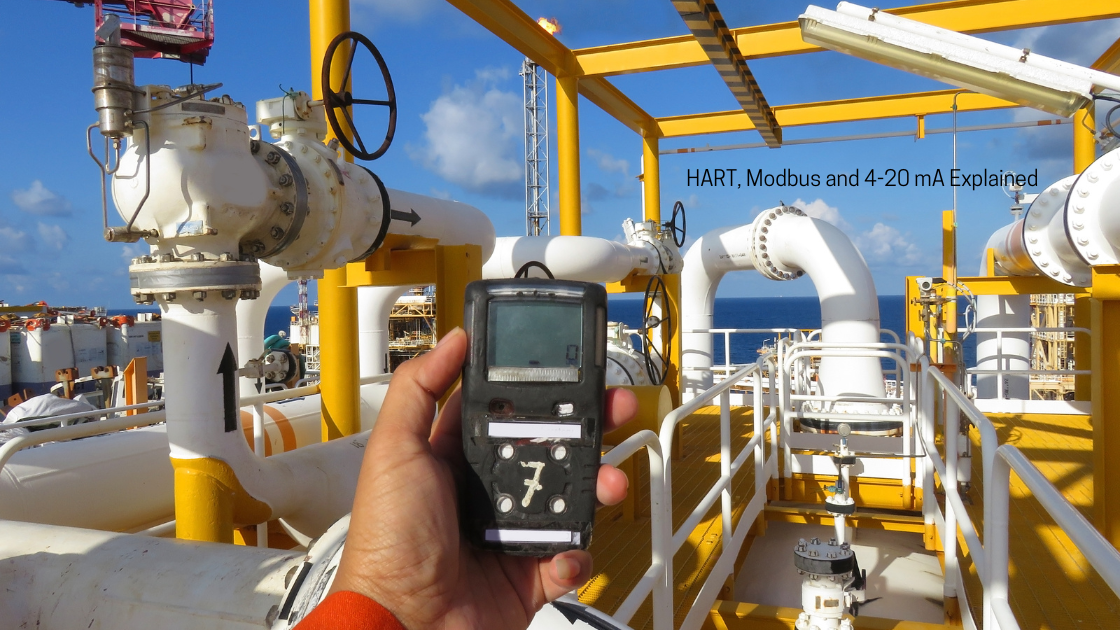
A gas detector is only as useful as the signal it delivers. The sensor can be perfect, but if the reading never reaches the control room, the PLC, or the fire and gas system in a form that can be trusted, it protects no one.
Three gas detector communication protocols dominate industrial sites: 4-20 mA analog, HART, and Modbus.
Most fixed detectors support at least one of them, and many support two. Choosing between them, or using them together, affects wiring cost, diagnostics, commissioning time, and how quickly you can find a fault at 3 a.m.
In this guide you will learn how each one works, how fault conditions are signaled, where each fits best, and the mistakes that cause most field problems.
What are the most common Gas Detector Communication protocols?
- 4-20 mA is the simple, robust analog standard. One loop carries one measurement and works nearly everywhere.
- HART rides on top of the same 4-20 mA loop and adds digital data such as diagnostics, calibration status, and configuration.
- Modbus (usually RS-485) is a digital network that lets many detectors share one cable and report rich data to a PLC, DCS, or SCADA.
Why the Communication Protocol Matters in Gas Detection
A fixed gas detector does three jobs: it senses gas, it decides what the reading means, and it tells someone. The third job is the protocol’s job.
The protocol you choose determines
What information leaves the detector
Only a gas concentration, or also sensor health, calibration due date, and fault codes?
How the system reacts to a failure
Can the controller tell the difference between “zero gas” and “dead detector”?
Installation cost
One cable per detector, or one cable for twenty?
Maintenance effort
Can a technician diagnose the unit from the control room, or does someone have to climb a ladder?
Getting this wrong tends to show up late, during commissioning or after the first false alarm.
4-20 mA: The Analog Workhorse
How the 4-20 mA signal works
A 4-20 mA gas detector converts its measurement into a current between 4 and 20 milliamps.
- 4 mA = zero gas (bottom of the measuring range)
- 20 mA = full scale (top of the measuring range)
- Everything in between is linear
The formula is:
Gas concentration = ((I − 4) ÷ 16) × full-scale range
Examples
| Detector range | Output current | Reading |
|---|---|---|
| 0–100 % LEL | 12 mA | 50 % LEL |
| 0–50 ppm H₂S | 8 mA | 12.5 ppm |
| 0–1000 ppm CO | 16 mA | 750 ppm |
Why “live zero” matters
The signal starts at 4 mA, not 0 mA, on purpose. This is called a live zero. If the current ever drops to 0 mA, the system knows something is wrong: a broken wire, a failed power supply, or a dead transmitter. A signal that started at 0 mA could not tell “no gas” from “no signal.”
Fault signaling on the 4-20 mA loop
The range below 4 mA and above 20 mA is used to signal conditions other than gas readings. Many manufacturers follow the NAMUR NE43 recommendation, which treats signals below roughly 3.6 mA or above roughly 21 mA as failures. Typical uses include:
- Fault (sensor failure, internal error)
- Inhibit or maintenance mode (during calibration or sensor replacement)
- Over-range (gas above the measuring range)
The exact values are manufacturer-specific. One detector may use 1 mA for a fault and 2 mA for calibration mode, while another uses different values. Always check the detector manual and set the receiving input card to match.
Wiring types: 2-wire, 3-wire, 4-wire
| Type | How it works | Typical use |
|---|---|---|
| 2-wire (loop powered) | Power and signal share one pair | Transmitters with low power consumption |
| 3-wire | Separate supply, signal and common | Catalytic and many infrared detectors |
| 4-wire | Separate power pair and signal pair | Higher-power devices, isolated outputs |
Another important detail is sourcing vs sinking. A sourcing output supplies the loop current itself, while a sinking output needs the loop to be powered by the receiver. Mismatch these and the reading will sit at 0 mA or at an unstable value.
Strengths and limits of 4-20 mA
Strengths
- Simple, universal, understood by every technician
- Immune to most electrical noise over long runs
- Works with practically every PLC, DCS, and F&G panel
- Easy to test with a handheld loop calibrator
Limits
- One measurement per pair of wires
- No built-in diagnostics beyond current levels
- Cannot change settings or read detailed status remotely
- Accuracy depends on analog-to-digital conversion at both ends
HART: Digital Intelligence on the Same Wires
What HART is
HART (Highway Addressable Remote Transducer) is a hybrid protocol. It keeps the standard 4-20 mA analog signal and adds a digital communication layer on top of it.
The digital signal uses frequency shift keying (FSK). A small AC signal at ±0.5 mA is superimposed on the loop, using 1200 Hz for a binary 1 and 2200 Hz for a binary 0.
Because the signal averages to zero, it does not disturb the analog reading. The control system still sees the same 4-20 mA gas concentration while HART data travels alongside it.
What HART adds to a gas detector
With a HART-enabled gas detector, a technician or asset management system can often read:
- The gas reading as a digital value (no loop conversion error)
- Sensor health and remaining life estimates
- Calibration status and last calibration date
- Device tag, serial number, and configuration
- Active fault codes and diagnostic messages
It also allows remote configuration. Alarm settings, ranges, and tags can often be changed from a handheld communicator, a laptop with a HART modem, or an asset management platform, without opening the enclosure in a hazardous area.
HART communication basics
- Master-slave structure: the host asks, the field device answers
- Up to two masters (for example, a control system and a handheld)
- Data rate of 1200 bps, which is slow but sufficient for diagnostics
- Needs a minimum loop resistance (typically around 230–600 Ω) for the signal to be detected correctly
- Variables are organized as PV, SV, TV, and QV (primary, secondary, tertiary, and quaternary variables)
Point-to-point vs multidrop
- Point-to-point: one device per loop, 4-20 mA still active. This is the most common use in gas detection.
- Multidrop: several devices share one pair of wires, with each loop current fixed at about 4 mA and all data digital. It is rarely used for gas detection, since it gives up the analog output that most safety systems depend on.
The catch: you need a way to read it
Many sites buy HART-capable detectors but never use the digital layer. The reasons are usually practical:
- The input cards do not pass HART data to the control system
- No HART multiplexer or asset management software is installed
- Technicians do not carry a HART communicator
If you plan to use HART, confirm the whole chain supports it, from detector to I/O card to software.
Modbus: Networking Many Detectors on One Cable
What Modbus is
Modbus is an open, serial-style protocol originally created in 1979. In gas detection you will most often see Modbus RTU over RS-485, and sometimes Modbus TCP over Ethernet.
Instead of one cable per detector, Modbus lets you connect many detectors to a single twisted-pair cable in a daisy chain.
How Modbus works
- A master (client), such as a PLC, gateway, or SCADA system, polls the devices.
- Each slave (server) has a unique address, from 1 to 247 on a Modbus RTU network.
- Data is stored in registers. The master reads or writes them by address.
A gas detector might expose registers like:
| Data | Typical register type |
|---|---|
| Gas concentration | Input or holding register |
| Alarm status (A1 / A2 / fault) | Coils or discrete inputs |
| Sensor status and fault codes | Holding registers |
| Calibration and configuration values | Holding registers |
RS-485 network rules that matter
- Shielded twisted pair cable, daisy-chained (not star)
- 120 Ω termination at both physical ends of the line
- Maximum length of roughly 1,200 m (4,000 ft) at lower baud rates
- A standard RS-485 segment supports up to 32 unit loads, and low-load transceivers allow more
- Every device must share the same baud rate, parity, and stop bits (for example 9600, 8N1, or 19200, 8E1)
Why there is no universal register map
This is the part that surprises many engineers. Modbus defines how data is exchanged, but not what each register means.
Every manufacturer publishes its own register map, so integrating a different brand of detector means reading a different table.
Pay attention to
- Register addresses (zero-based vs one-based numbering)
- Data types (16-bit integer, 32-bit float)
- Byte and word order for floating-point values
- Scaling factors (for example, a value of 250 meaning 25.0 ppm)
Strengths and limits of Modbus
Strengths
- Far less cable on large installations
- Rich data: readings, status, diagnostics, configuration
- Open, widely supported, easy to integrate with PLCs and SCADA
- Supports remote configuration on many devices
Limits
- Polling is slower and less deterministic than a dedicated analog loop
- A cable break or bad termination can affect many detectors at once
- No standard data model, so integration takes engineering time
- Not a direct replacement for hardwired safety signals in most safety functions
4-20 mA vs HART vs Modbus: Comparison Table
| Feature | 4-20 mA | HART | Modbus RTU (RS-485) |
|---|---|---|---|
| Signal type | Analog | Analog + digital | Digital |
| Data per device | 1 value | Multiple variables + diagnostics | Many registers |
| Devices per cable | 1 | 1 (point-to-point) | Many (daisy chain) |
| Remote diagnostics | Very limited | Yes | Yes |
| Remote configuration | No | Yes | Often yes |
| Wiring cost | Highest on large sites | Same as 4-20 mA | Lowest on large sites |
| Speed | Continuous | 1200 bps digital | Depends on polling and baud rate |
| Fault detection | Current outside 4-20 mA | Current + digital status | Communication timeout + status registers |
| Needs special hardware | No | HART modem / HART-capable I/O | Serial port or gateway |
| Common role | Primary alarm and control signal | Maintenance and asset management | Monitoring and SCADA integration |
Safety Systems, SIL, and Which Signal to Trust
For gas detectors used in a safety instrumented function, the analog 4-20 mA signal into a safety-rated input is the long-established method. It is simple, continuously monitored by the live zero, and easy to prove in a safety lifecycle.
Digital protocols are widely used alongside it, usually for diagnostics, monitoring, and asset management, not as the sole path for the safety action. A typical architecture is:
- 4-20 mA (or relay outputs) carries the gas reading to the fire and gas controller or safety PLC.
- HART or Modbus feeds the same detector’s health and configuration data to the maintenance and monitoring systems.
If you intend to use a digital protocol as part of a safety function, the detector, the communication path, and the logic solver need to be certified and applied for that purpose according to IEC 61508 and the manufacturer’s safety manual.
Always follow the safety manual for the specific device and do not assume a protocol is acceptable for a SIL-rated loop because it works in the field.
How to Choose the Right Protocol
Use these questions to decide.
Choose 4-20 mA when
- The detector feeds a fire and gas panel, safety PLC, or alarm controller
- You need maximum simplicity and compatibility
- The site has few detectors or they are far apart
Add HART when
- You want diagnostics and remote configuration without extra cabling
- Your I/O cards and software can actually read the HART data
- You manage detectors through an asset management system
Choose Modbus when
- You have many detectors in one area (tank farms, battery rooms, parking garages, process halls)
- You want to cut cable and installation costs
- You need rich status data in SCADA or BMS
- The detectors are not the only path for safety actions
Combine them when
- You want a hardwired 4-20 mA signal for alarms and Modbus or HART for maintenance data. This is very common and is often the best of both worlds.
Common Wiring and Configuration Mistakes
Based on typical commissioning problems, these are the issues that show up most often.
4-20 mA
- Sink/source mismatch: the detector and input card both expect to supply power, or neither does.
- Wrong fault range: the input card is not configured to recognize the detector’s fault current, so a failed unit looks like a normal low reading.
- Ground loops: multiple grounds on the shield create noisy or drifting readings.
- Loop resistance too high: long cable plus a high-impedance input leaves too little voltage for the transmitter.
HART
- Loop resistance outside the HART range: communication is intermittent or impossible.
- Filters or isolators that block HART: some barriers and signal conditioners strip the digital signal.
- Wrong polling address: the host is looking for address 0 but the device is set elsewhere.
Modbus
- Mismatched baud rate, parity, or stop bits.
- Duplicate addresses on the same bus.
- Missing or doubled termination resistors.
- Star wiring instead of daisy chain.
- Byte or word order errors that turn a valid float into nonsense numbers.
- Offset errors from zero-based vs one-based register addressing.
Troubleshooting Checklist
When a detector’s signal looks wrong, work from simple to complex.
- Check the power supply at the detector, not just at the panel.
- Measure the loop current with a multimeter or loop calibrator. Is it inside 4–20 mA, or at a fault level?
- Confirm sink/source wiring against the manual.
- Verify the input card scaling matches the detector range (for example, 0–100 % LEL).
- Inject a known current (such as 12 mA) at the detector end and confirm the control system shows 50 % of range.
- For HART, connect a communicator and verify the device responds. Check loop resistance.
- For Modbus, confirm address, baud rate, parity, and termination. Read a single known register first.
- Review the detector’s own diagnostics for sensor faults, calibration errors, or overdue calibration.
If readings drift or zero looks unstable even though communication is fine, the problem may be the sensor, not the signal. See our guide on troubleshooting zero and span issues in gas sensors.
Where This Is Going: Digital Data and IIoT
Gas detection is gradually moving toward more digital data: fleet management platforms, predictive maintenance, wireless networks, and cloud dashboards.
4-20 mA is not disappearing, but it increasingly serves as the reliable safety path while Modbus, HART, and IP-based protocols carry the information used to maintain the system.
The practical takeaway is to treat the analog loop as the dependable backbone and the digital layers as the way to get more value out of your detectors.
Key Takeaways
- 4-20 mA is simple, universal, and the standard for alarm signals into safety systems.
- HART adds diagnostics and configuration over the same wires, but only helps if your system can read it.
- Modbus reduces cabling and provides rich data across many detectors, but needs careful network and register-map setup.
- Many sites use 4-20 mA for the alarm path and HART or Modbus for maintenance and monitoring.
- Match fault current ranges, loop wiring, and network settings to the manufacturer’s manual before you commission.
Frequently Asked Questions
What does 4-20 mA mean in a gas detector?
It is an analog current signal where 4 mA represents zero gas and 20 mA represents the full-scale reading.
The signal is linear, so 12 mA is 50 % of the range. Currents outside 4–20 mA are commonly used to indicate faults or maintenance mode.
Is HART a digital or analog protocol?
Both. HART keeps the 4-20 mA analog signal and superimposes a digital FSK signal on top of it, so the same two wires carry the gas reading and extra digital data.
Can a gas detector use Modbus and 4-20 mA at the same time?
Yes, many detectors offer both outputs. A common design uses 4-20 mA for alarm signals to the safety system and Modbus for monitoring, diagnostics, and SCADA integration.
What is the difference between Modbus RTU and Modbus TCP?
Modbus RTU runs over serial lines such as RS-485. Modbus TCP runs over Ethernet networks. The data model is similar, but TCP uses IP addresses and standard network infrastructure instead of serial addresses and baud rates.
Why does my gas detector read 0 mA?
A current of 0 mA usually means a broken wire, a failed power supply, or a dead transmitter. Because a healthy detector never drops below 4 mA in normal operation, 0 mA is treated as a fault. Check the wiring, power, and polarity first.
Is HART or Modbus better for gas detectors?
Neither is universally better. HART is ideal when you want diagnostics over existing 4-20 mA wiring. Modbus suits large installations that benefit from shared cabling and richer data.
The right choice depends on your system architecture, the number of detectors, and what your control platform supports.
Which protocol should I use for a SIL-rated gas detection loop?
The 4-20 mA signal into a safety-rated input is the traditional choice. Digital protocols can supplement it, but their use in a safety function must follow the detector’s safety manual and the applicable IEC 61508 and IEC 61511 requirements.
Conclusion
4-20 mA, HART, and Modbus are not competitors so much as tools with different jobs. The analog loop delivers a dependable alarm signal.
HART opens a window into the detector without adding wires. Modbus connects many detectors to the systems that monitor them.
Understanding how each one carries information, and how each one fails, makes commissioning faster and troubleshooting far less painful.
Before your next installation, check the manual for the detector’s fault current levels, confirm your input cards can read what the detector sends, and decide which protocol carries the safety signal and which carries the maintenance data.
Have a question about wiring a specific detector or integrating it with your control system? Leave a comment below.