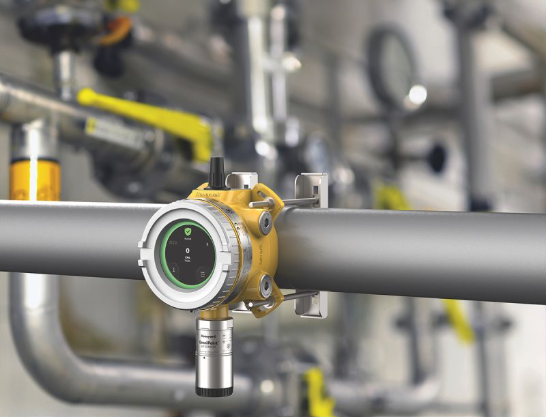
A gas release in a chemical plant rarely announces itself. A flange gasket weeps, a pump seal degrades, a relief valve lifts, and within seconds an invisible cloud can drift toward people, ignition sources or a control room air intake.
Gas detection in chemical plants is the layer of protection that turns that invisible hazard into an alarm, a shutdown or an evacuation in time to matter.
But owning detectors is not the same as having a working gas detection system. In my experience as an automation engineer working with gas detection and safety systems, the plants with the best safety records are not the ones with the most expensive hardware.
They are the ones that apply a handful of disciplined practices consistently: assessing hazards properly, choosing the right technology, placing detectors where gas will actually go, setting sensible alarms, and keeping every sensor verified and healthy.
This guide walks through those best practices step by step.
Start with a gas hazard assessment
Every good gas detection design begins with a clear answer to one question: what can leak, where, and what happens next?
Use your existing process safety work (HAZOP, LOPA, process hazard analysis) as the foundation, then build a gas-specific view on top of it:
Identify every hazardous gas and vapor
Flammable (hydrocarbons, hydrogen, solvent vapors), toxic (hydrogen sulfide, chlorine, ammonia, carbon monoxide, hydrogen chloride, phosgene) and oxygen deficiency or enrichment.
Record the properties that drive detection
Vapor density relative to air, lower explosive limit (LEL), exposure limits (TWA, STEL, IDLH), pressure, temperature and boiling point.
Map release scenarios
Flange and valve leaks, pump and compressor seals, loading and unloading, sample points, vents, relief discharges, tank breathing and process upsets.
Identify what needs protection
Operators, nearby communities, control rooms, motor control centers, ignition sources and critical equipment.
Define the safety objective for each scenario
Is the detector there to trigger an alarm, a shutdown, ventilation, deluge or evacuation? The objective determines the required speed, reliability and voting logic.
Document this assessment. It becomes the basis for your detector layout, your alarm philosophy and your auditing evidence later.
Choose the right sensing technology
No single sensor works for every gas or every environment. Choosing technology is a trade-off between selectivity, response time, maintenance burden and failure behavior.
| Technology | Typical use | Strengths | Limitations |
|---|---|---|---|
| Catalytic bead | Flammable gases and vapors (%LEL) | Proven, low cost, broad hydrocarbon response | Can be poisoned (silicones, H2S, chlorinated compounds), needs oxygen, can fail silently if not tested |
| Infrared (NDIR) point | Hydrocarbons, CO2 | Not poisoned, works without oxygen, self-diagnostics | Not suitable for hydrogen, can be affected by condensation or fouled optics |
| Open-path / line-of-sight IR | Perimeters, large areas, long leak paths | Covers wide areas, fast detection of gas crossing the beam | Affected by fog, heavy rain and misalignment, measures path-integrated concentration |
| Electrochemical | Toxic gases (H2S, CO, Cl2, NH3) and oxygen | Specific, sensitive at ppm levels, low power | Limited life, affected by temperature, humidity and cross-sensitivity, needs regular calibration |
| PID (photoionization) | VOCs at low ppm | Very sensitive to many organics | Not specific, lamp and window fouling, humidity effects |
| Metal oxide semiconductor | Hydrogen and some toxic gases | Rugged and long-lived in some applications | Cross-sensitivity, baseline drift |
| Ultrasonic leak detection | High-pressure gas leaks | Detects the sound of the leak, not the gas, works in wind | Does not measure concentration, background noise must be assessed |
| UV/IR flame detectors | Fire from flammable liquids and gases | Fast flame detection | Detects flame, not gas, needs a clear line of sight |
A few practical rules:
- Use two technologies where one failure mode is unacceptable. For example, combining infrared point detectors with open-path detectors, or catalytic with infrared, reduces common-cause failure.
- Prefer sensors with diagnostics. Detectors that self-check optics, report sensor health and signal faults over HART or digital protocols are far easier to keep reliable.
- Look at what can poison or foul the sensor in your specific process before you decide. A catalytic sensor in a plant with silicone or sulfur compounds needs a deliberate plan.
- Verify the certification. Detectors in hazardous areas must carry the appropriate approval for the area classification (for example ATEX/IECEx or the North American equivalent), and detector performance should be tested to the relevant standard such as IEC 60079-29-1 for flammable gas detectors.
Place detectors where gas will actually go
Poor placement is one of the most common reasons a technically good system fails in practice. The detector can be perfectly calibrated and still never see the leak.
Consider gas density
- Lighter than air (hydrogen, methane, ammonia): mount detectors high, near ceilings, roof peaks and ventilation exhausts.
- Heavier than air (propane, butane, chlorine, hydrogen sulfide, most solvent vapors): mount detectors low, near grade, pits, trenches, sumps and low-lying areas where gas collects.
- Near neutral density (carbon monoxide): mount in the breathing zone and near likely sources.
Remember that temperature, pressure and mixing can change this behavior. A cold, pressurized release of a light gas may initially travel downward. Always confirm placement with release scenarios rather than density alone.
Focus on leak sources and receptors
- Place detectors near likely leak sources: compressors, pumps, flanged connections, valve manifolds, loading arms and sample stations.
- Place detectors at receptors: air intakes for control rooms, switchrooms and analyzer shelters, and near ignition sources such as furnaces, generators and non-rated electrical equipment.
- For toxic gases, place detectors between the source and the people you are protecting, not only at the source.
Respect airflow and the environment
- Study prevailing wind direction, ventilation patterns, obstructions, enclosures and dead zones.
- Use scenario-based and geographic coverage approaches together. Scenario-based coverage targets credible leaks, while geographic coverage looks for the area that a gas cloud of a defined size could reach. Guidance such as ISA-TR84.00.07 describes how to evaluate the effectiveness of gas detection coverage.
- Install detectors where technicians can reach them for testing and calibration. A detector that is difficult to access will eventually be tested less often.
Use 3D gas dispersion modeling or CFD for complex, congested or high-consequence areas. It is much cheaper than discovering a blind spot after an incident.
Read: Gas Detector Mounting Height Guide: Where to Install Gas Detectors and Why?
Set alarm levels and response actions with intent
Alarm setpoints should be derived from hazard data and the response you want, not copied from another plant.
| Hazard | Common practice (examples only) | Notes |
|---|---|---|
| Flammable gas | Low alarm around 10 to 25% LEL, high alarm around 40 to 60% LEL | Higher stages typically trigger shutdown or ventilation actions |
| Oxygen deficiency | Alarm at 19.5% O2 | Common regulatory reference for oxygen-deficient atmospheres |
| Oxygen enrichment | Alarm at 23.5% O2 | Enriched atmospheres increase fire risk |
| Toxic gases | Based on TWA, STEL and IDLH values | For example, H2S, Cl2 and NH3 each need setpoints tied to their own exposure limits and local regulations |
Treat these as starting points. Your site’s risk assessment, local regulations and manufacturer data decide the final values.
Good alarm design also means
Define a response for every alarm level
Who does what at low alarm? What automatically happens at high alarm?
Use voting logic for shutdown functions
Two-out-of-three (2oo3) or two-out-of-two (2oo2) voting reduces spurious trips, while one-out-of-two (1oo2) favors safety. Choose according to the consequence of both a missed event and a false trip.
Apply alarm management principles
Rationalize alarms against standards such as ISA-18.2 so operators are not buried in nuisance alarms.
Make fault signals distinct from gas alarms
A detector in fault must never look like a detector reading zero.
Design for functional safety (SIL) where required
When gas detection initiates a safety instrumented function, such as isolating a feed or shutting down a compressor, it becomes part of a safety instrumented system and must be designed accordingly.
- Follow IEC 61511 for process industry safety instrumented systems and IEC 61508 for the devices themselves.
- Select detectors with appropriate SIL capability and proven failure data (for example, SIL 2 certified detectors where the risk assessment demands it).
- Calculate the required probability of failure on demand and set proof test intervals that actually meet it.
- Remember that SIL is a system property. The detector, the transmitter, the wiring, the logic solver and the final element all contribute.
In regions covered by process safety regulations such as OSHA PSM (29 CFR 1910.119) or the EPA RMP rule in the United States, documented gas detection, maintenance and testing are also part of demonstrating compliance.
Bump test, calibrate and document
The most common reason gas detection fails is not bad design. It is lack of verification.
Bump (functional) testing exposes the detector to a known gas concentration to confirm it responds and alarms. Calibration adjusts the detector’s reading to match a known standard.
- Portable detectors: industry guidance, such as the ISEA statement on verification of calibration, recommends a bump test before each day’s use.
- Fixed detectors: functional checks and calibration intervals are commonly in the range of every three to six months, but should be set from manufacturer instructions, sensor history, the environment and the safety function.
- Use certified calibration gas within its expiry date, with the correct regulator and flow rate for the sensor, and the correct test gas or a verified surrogate for the target gas.
- Test the full loop. Include alarm outputs, shutdown logic, beacons, horns and DCS indication, not just the sensor reading.
- Record everything. Date, technician, gas used, as-found and as-left readings, and any sensor replacement. Trend as-found results. A sensor that repeatedly needs large span adjustments is telling you it is near end of life.
If zero or span readings become hard to correct, see my guide on troubleshooting zeroing and span issues in gas sensors.
And if you are seeing declining response, review the signs a gas sensor needs replacement before the next scheduled calibration.
Manage sensor life, poisoning and environmental effects
Sensors age and the plant environment accelerates it.
- Catalytic sensors can lose sensitivity through poisoning or inhibition by silicones, sulfur compounds, lead and halogenated compounds. Regular testing with the target gas is essential.
- Electrochemical sensors have a finite life and can dry out or saturate in extreme humidity and temperature.
- Infrared sensors can be affected by dirty optics, condensation and misalignment.
- Weather protection: use sunshields, splash guards, dust screens and appropriate collecting cones, but verify they do not slow the response to gas.
- Cross-sensitivity: know which interferents your sensors respond to, such as hydrogen on a CO sensor, to avoid false alarms and false confidence.
Track sensor installation dates and plan replacements proactively rather than waiting for failure.
Integrate detection into your control and safety architecture
Detectors work best as part of a coordinated system.
- Connect to the fire and gas system and the DCS or PLC so alarms, faults and diagnostics are visible to operators and trigger the correct automated actions.
- Use diagnostic-rich signals. A 4-20 mA signal with NAMUR NE43-style fault levels (for example, below about 3.8 mA) lets the system distinguish a fault from a true zero. HART or Modbus communication adds device health, calibration status and remote configuration.
- Supervise the wiring and power. Open circuits, short circuits and loss of power must be detected and alarmed.
- Coordinate with other layers. Link gas alarms to ventilation, isolation valves, emergency shutdown, deluge or water curtains and public address systems as your safety philosophy requires.
- Consider data analytics and fleet management. Centralized software for portable and fixed devices makes bump test compliance, calibration schedules and event history much easier to manage and audit.
Don’t forget portable and personal gas monitoring
Fixed detection protects areas. Portable and personal detectors protect people, especially during maintenance, turnarounds and confined space entry.
- Issue multi-gas personal monitors (typically O2, LEL, CO and H2S, plus additional sensors as needed) to personnel entering process areas.
- For confined space entry, test the atmosphere in the correct order: oxygen first, then flammable gases, then toxic gases, and test at multiple levels because gases can stratify.
- Make sure the detector, sampling pump and tubing are suitable for the task, and keep continuous monitoring in place during the work.
- Link portable detector use to your permit-to-work system.
Train people and test the response
A perfect detector layout still fails if people do not know what the alarms mean.
- Train operators, maintenance technicians and emergency teams on each alarm level and the required action.
- Run drills that include gas alarms, shelter-in-place, evacuation and rescue scenarios.
- Include gas detection in your management of change process so new equipment, modifications or process changes trigger a review of coverage.
- Audit the system regularly and review incidents and near misses for lessons.
Common mistakes to avoid
- Placing detectors on a uniform grid without considering density, airflow or leak sources.
- Skipping bump tests and relying only on scheduled calibration.
- Using the wrong calibration gas or an expired cylinder.
- Ignoring sensor poisoning, cross-sensitivity and environmental effects.
- Setting alarms so low or so many that operators ignore them.
- Treating fault signals as non-events.
- Failing to update coverage after process or layout changes.
- Leaving test and maintenance records incomplete, which makes audits and root cause analysis harder.
Quick checklist for chemical plant gas detection
| Area | Question to ask |
|---|---|
| Hazard assessment | Have all gases, release scenarios and receptors been documented? |
| Technology | Is each sensor type suitable for the gas, environment and failure mode? |
| Placement | Are detectors positioned by density, leak sources, airflow and ignition sources? |
| Alarms | Are setpoints justified and every alarm tied to a defined action? |
| Functional safety | Do safety functions meet the required SIL and proof test intervals? |
| Verification | Are bump tests, calibration and full-loop tests scheduled and documented? |
| Maintenance | Are sensor age, poisoning risk and environmental protection managed? |
| Integration | Are faults, alarms and diagnostics visible in the control system? |
| People | Is training current and are drills realistic? |
| Change control | Is coverage reviewed whenever the plant changes? |
Frequently asked questions
What is the best type of gas detector for a chemical plant?
There is no single best type. Chemical plants typically use a combination: infrared or catalytic detectors for flammable gases, electrochemical sensors for toxic gases and oxygen, open-path detectors for large areas, and portable monitors for personnel. The right mix depends on the gases present, the environment and the required safety function.
How often should gas detectors be calibrated in a chemical plant?
Follow the manufacturer’s instructions and your risk assessment. Portable detectors should be bump tested before each day’s use.
Fixed detectors are commonly calibrated every three to six months, with more frequent checks in harsh environments or where sensors are prone to drift.
What is the difference between a bump test and calibration?
A bump test confirms the detector responds to gas and triggers its alarms. Calibration adjusts the detector so that its reading matches a known gas concentration. Bump testing verifies function, while calibration restores accuracy.
How many gas detectors do I need?
The number depends on plant layout, leak sources, airflow and the coverage target defined in your assessment.
Instead of using a rule of thumb, use scenario-based and geographic coverage analysis, often supported by dispersion modeling.
Are fixed gas detectors enough, or do I also need portable detectors?
You need both. Fixed detectors monitor process areas continuously, while portable and personal detectors protect individuals during maintenance, inspection and confined space entry where fixed coverage cannot reach.
Which standards apply to gas detection in chemical plants?
Common references include IEC 60079-29-1 (performance of flammable gas detectors), IEC 60079-29-2 (selection, installation, use and maintenance), IEC 61511 and IEC 61508 (functional safety), ISA-TR84.00.07 (effectiveness of fire and gas systems) and local regulations such as OSHA PSM or equivalent. Always confirm the standards required in your jurisdiction.
Final thoughts
Effective gas detection in chemical plants is not a product you buy once. It is a lifecycle: assess the hazard, select and place the right detectors, set meaningful alarms, integrate with your safety systems, then verify and maintain relentlessly.
Plants that treat gas detection as a living system, supported by good data and well-trained people, are the ones that catch small leaks before they become incidents.
If you are reviewing an existing system, start with the checklist above and be honest about where the gaps are. A single missed bump test program or an outdated detector layout can matter more than any upgrade in hardware.
Disclaimer
This article is for general educational purposes. Always follow applicable regulations, manufacturer instructions and your site’s engineered safety requirements, and consult qualified safety professionals for specific designs.