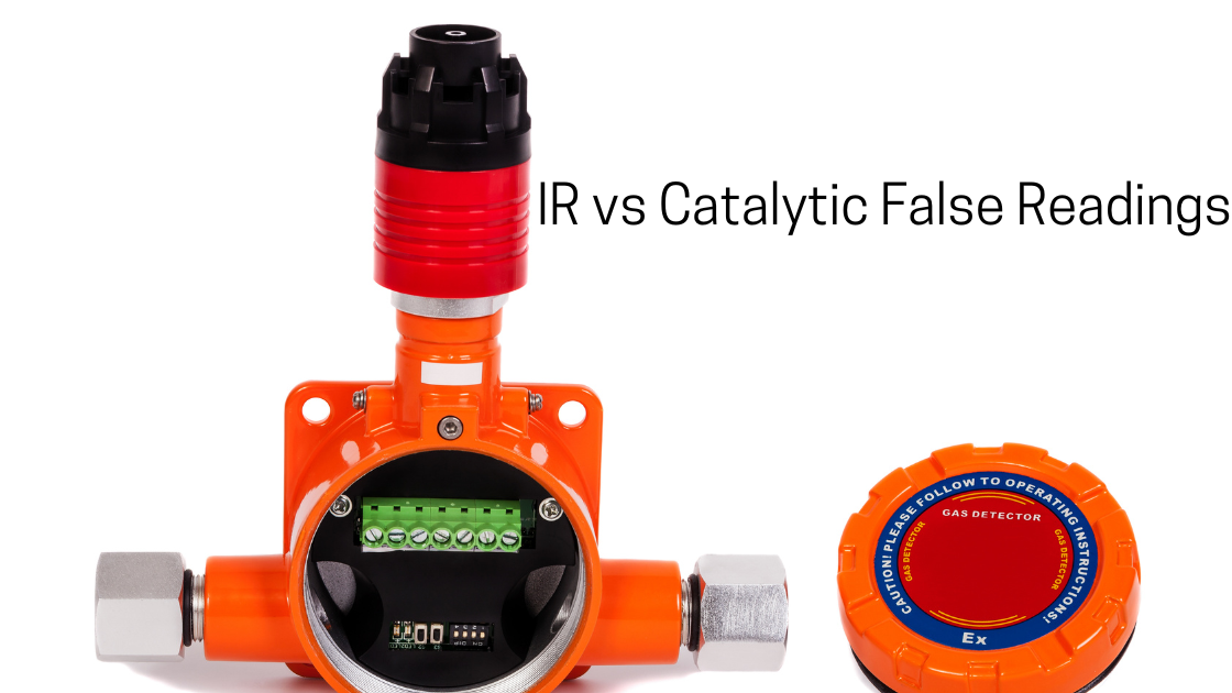
A combustible gas detector that reads 20% LEL in a clean area, or reads zero during a real leak, is a safety problem and an operational one. False alarms erode trust, and false lows can be dangerous.
Infrared (IR) and catalytic bead detectors both measure combustible gas as %LEL, but they fail in very different ways.
If you treat every bad reading the same, you will waste time swapping sensors that were never the problem.
This guide explains how each technology produces false readings and gives you a repeatable method to find the root cause.
How Each Technology Works (and Why It Matters for Troubleshooting)
Catalytic bead (pellistor) sensors
A catalytic sensor has two beads in a Wheatstone bridge: an active bead coated with a catalyst and a reference bead that is deliberately inert.
Combustible gas burns on the active bead, raising its temperature and resistance. The bridge imbalance is proportional to gas concentration.
Because the sensor depends on combustion, it:
- Needs oxygen to respond correctly.
- Is vulnerable to poisoning and inhibition (silicones, hydrogen sulfide, sulfur compounds, lead, chlorinated and halogenated compounds).
- Is not inherently fail-safe. A poisoned sensor can look healthy in clean air while losing sensitivity to gas.
Infrared (NDIR) sensors
An IR detector measures how much infrared light a hydrocarbon gas absorbs, typically near 3.4 µm.
A second reference wavelength compensates for changes in source intensity and some optical contamination.
Because the sensor depends on light transmission, it:
- Does not need oxygen and is not poisoned by silicones or sulfur.
- Usually has strong self-diagnostics. A blocked or degraded optical path is generally flagged as a fault, which makes IR closer to fail-safe.
- Cannot detect hydrogen, which does not absorb IR in the relevant band.
- Is sensitive to the optical path: dirt, condensation, ice, misalignment, or interfering IR sources.
Quick Comparison: Typical False Reading Causes
| Symptom | Catalytic bead: common causes | IR: common causes |
|---|---|---|
| False high / spikes | Cross-sensitivity to other flammable vapors, rapid temperature or humidity swings, electrical noise, wiring faults, zero drift | Condensation or fogging on optics, strong IR sources (sun, flares, welding), incorrect gas calibration curve, electrical noise |
| False low / no response | Sensor poisoning or inhibition, oxygen deficiency, aged or degraded beads, wrong gas calibration factor | Heavily contaminated optics, wrong gas setting, hydrogen (not detectable), misaligned open-path beam |
| Slow drift | Bead aging, repeated gas exposure, reference bead mismatch | Source aging, gradual window contamination |
| Stuck at a value | Failed bridge, wiring or power fault, controller configuration issue | Failed electronics, latched fault condition, output stuck at fault current |
| Fault instead of reading | Open or shorted bridge | Loss of signal strength, source failure, blocked beam |
Step-by-Step Root Cause Process
Step 1: Classify the symptom
Write down exactly what you see before touching anything:
- Is the reading too high, too low, drifting, spiking, or frozen?
- Is it constant or intermittent?
- Does it correlate with time of day, weather, process steps, or maintenance activity?
Intermittent spikes usually point to the environment or electrical causes. Constant offsets point to calibration or sensor condition. Gradual changes point to aging or contamination.
Step 2: Verify with an independent reference
Use a calibrated portable detector, ideally one using a different technology, to check the area. This tells you whether the gas is actually present or the fixed detector is wrong.
If the portable reads zero and the fixed detector reads 15% LEL, you have a false high. If a known leak is confirmed and the fixed detector reads zero, treat it as a false low and a safety priority.
Step 3: Review the environment and recent changes
Ask what changed:
- New cleaning chemicals, lubricants, sealants, or aerosols (silicones are a classic catalytic poison).
- New process vapors that could cause cross-sensitivity.
- Washdowns, heavy rain, steam, or condensation, which matter most for IR optics.
- Welding, flaring, or intense sunlight near IR detectors.
- New VFDs, radios, or high-power equipment that could introduce electrical noise.
Many “mystery” false readings turn out to coincide with a change someone forgot to mention.
Step 4: Check zero in confirmed clean air
Apply zero air (or confirm clean ambient air) and observe the reading.
- Zero offset in clean air: suspect drift, contamination, or an electrical issue.
- Correct zero but no gas response: suspect poisoning (catalytic) or a gas setting problem (IR).
Never zero a detector in an atmosphere that might contain background gas. Zeroing in a contaminated area bakes a false low into every later reading.
Step 5: Perform a bump test, then a calibration check
Apply a known concentration of the correct test gas and check:
- Response level: does it reach the expected value within tolerance?
- Response time (T50/T90): a slow response is an early sign of a poisoned catalytic sensor or a clogged flame arrestor or filter.
For catalytic detectors, regular bump testing matters more because poisoning does not always trigger a fault. For IR, a passing bump test combined with healthy diagnostics is strong evidence the sensor is sound.
Step 6: Inspect the diagnostics and raw signal
Where the detector provides diagnostic data, use it:
- Catalytic: bridge balance, sensor current or voltage, sensitivity indicators.
- IR: active/reference signal ratio, optical signal strength, source health, internal temperature.
A falling signal strength on an IR detector with an otherwise normal reading usually means the optics need cleaning. A catalytic sensor needing excessive adjustment to hit span is a sign of aging or poisoning.
Step 7: Inspect wiring, power, and the control system
Sensors are blamed for plenty of faults that live elsewhere:
- Verify supply voltage at the detector, not only at the panel.
- Check for water ingress, corroded terminals, loose conductors, and damaged cable.
- Confirm shield and grounding practices to reduce EMI.
- Verify 4–20 mA loop integrity and confirm the controller’s scaling, range, gas type, and fault-current thresholds match the detector.
A mismatch between the detector’s output and the controller’s scaling can produce a perfectly “wrong” reading from a perfectly healthy sensor.
Step 8: Confirm gas type and response factors
Both technologies respond differently to different hydrocarbons. A detector calibrated for methane will not read propane, butane, or heavier vapors accurately unless the right correction factor or calibration gas is used. Always confirm the target gas, calibration gas, and configured gas curve all agree.
Step 9: Replace, correct, or redesign
Only after the above should you replace the sensor. If the root cause was environmental (poisons, condensation, interference), a replacement will fail the same way unless you also.
- Move the detector or add weather protection.
- Change the technology (for example, IR where poisons are present).
- Remove or replace the offending chemical.
- Adjust the maintenance interval.
Choosing Between IR and Catalytic to Prevent False Readings
- Choose IR where silicones, sulfur compounds, or other poisons are present, where oxygen may be low or absent (inerted or enriched atmospheres), where fail-safe diagnostics are valued, or where maintenance access is difficult.
- Choose catalytic where hydrogen must be detected, where a broad range of flammable gases is expected, or where cost and simplicity are the priority and a disciplined bump-test regime is in place.
- Use both in critical areas where diversity of technology adds confidence and makes false readings easier to spot.
Whichever you choose, follow the relevant selection, installation, and maintenance guidance in standards such as IEC 60079-29-1 and IEC 60079-29-2, and the manufacturer’s instructions.
Preventive Practices
- Bump test at defined intervals and after any exposure event.
- Keep records of zero and span adjustments, because trends reveal aging early.
- Protect sensors from known poisons and liquid ingress.
- Clean IR optics according to the manufacturer’s procedure.
- Use the correct calibration gas and flow rate every time.
- Document and review every false alarm instead of just resetting it.
Frequently Asked Questions
Can a catalytic sensor be poisoned without any fault alarm?
Yes. This is one of its key weaknesses, and why regular bump testing is essential.
Why does my IR detector read high after rain or washdown?
Moisture or condensation on the optics can change light transmission. Good compensation reduces this, but heavy contamination can still cause errors or faults.
Can an IR detector see hydrogen?
No. Standard IR hydrocarbon detectors do not detect hydrogen. Use another technology for hydrogen hazards.
Is zero drift always a sensor problem?
No. Temperature changes, wiring problems, power issues, and controller scaling can all mimic drift.
How often should I calibrate?
Follow the manufacturer’s recommendation and your site risk assessment. Bump test frequency should reflect the application’s exposure to poisons, contamination, and process upsets.
Conclusion
False readings are symptoms, not causes. Catalytic detectors tend to fail through chemistry (poisoning, inhibition, aging), while IR detectors tend to fail through optics (contamination, condensation, interference).
Classify the symptom, verify with an independent instrument, check zero and span, review diagnostics, and rule out wiring and configuration before replacing hardware.
That discipline reduces nuisance alarms and, more importantly, makes sure a real gas event is never missed.
Disclaimer: This article is general guidance. Always follow the manufacturer’s documentation, your site procedures, and applicable standards and regulations.